
Speech Coding System to Improve Packet Loss Concealment

a speech coding and packet loss technology, applied in the field of speech coding system to improve packet loss concealment, can solve the problems of sacrificing too much quality, requiring a much higher bit rate, and propagating errors for quite a long tim

Active Publication Date: 2008-06-26
HUAWEI TECH CO LTD
View PDF3 Cites 55 Cited by
  • Summary
  • Abstract
  • Description
  • Claims
  • Application Information

AI Technical Summary

Benefits of technology

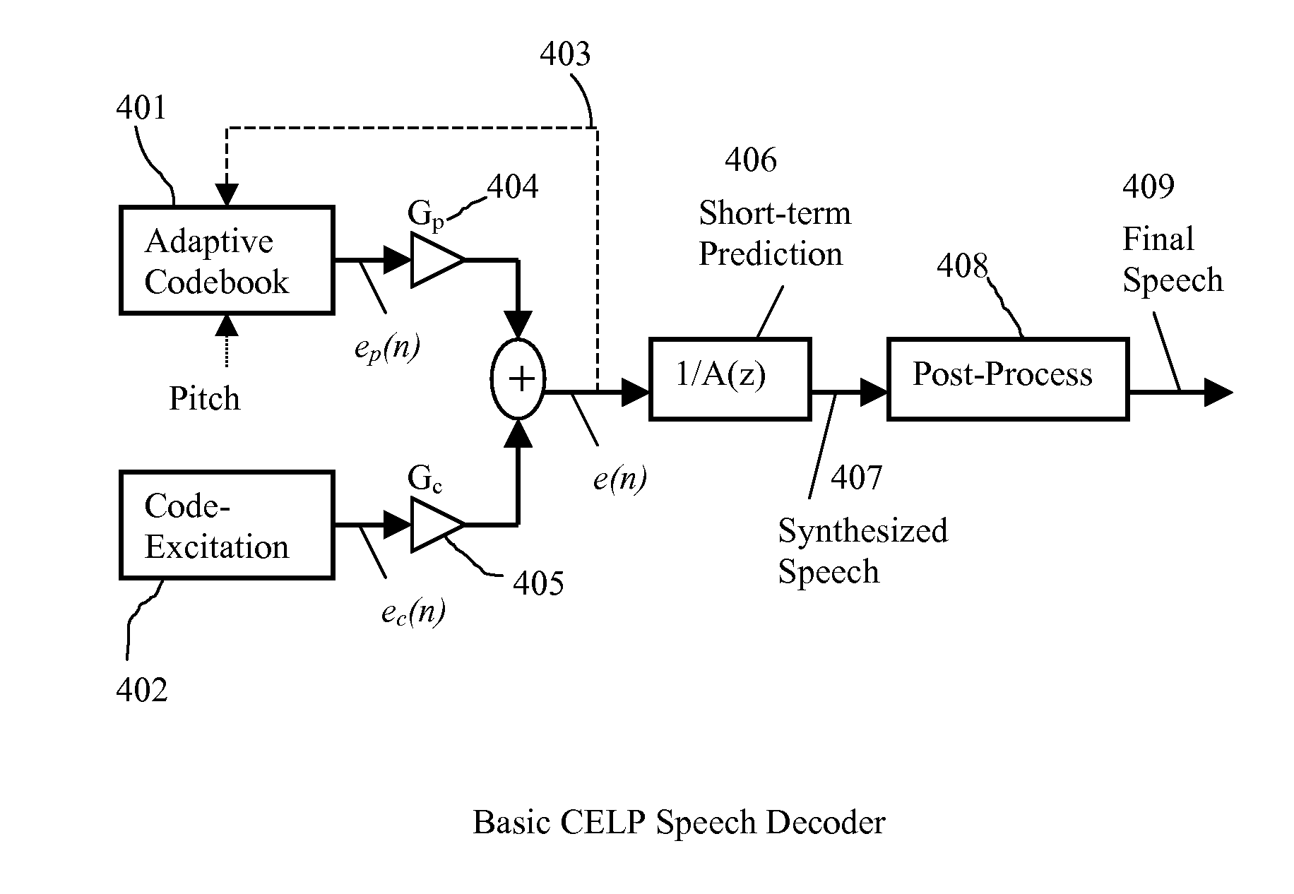
[0013]For most voiced speech, one frame contains more than 2 pitch cycles. If the speech is very voiced, a compromised solution to avoid the error propagation while still profiting from the significant long-term prediction is to limit the pitch gain maximum value for the first pitch cycle of each frame. We can classify speech signal into different cases and treat them differently. For example, Class 1 is defined as (strong voiced) and (pitch<=subframe size); Class 2 is defined as (strong voiced) and (pitch>subframe & pitch<=half frame); Class 3 is defined as (strong voiced) and (pitch>half frame); Class 4 represents all other cases. In case of Class 1, Class 2, or Class 3, for the subframes which cover the first pitch cycle within the frame, the pitch gain is limited to a maximum value (depending on Class) much smaller than 1, and the coded excitation codebook size should be larger than other subframes within the same frame, or one more stage of code-excitation is added to compensate for the lower pitch gain. For other subframes rather than the first pitch cycle subframes, or for Class 4, a regular CELP algorithm is used. The Class index (class number) assigned above to each defined class can be changed without changing the result.

Problems solved by technology

If the previous bit-stream packet is lost and the pitch gain Gp is high, the incorrect estimate of the previous synthesized excitation could cause error propagation for quite long time after the decoder has already received the correct bit-stream packet.
Although this kind of solution solved the error propagation problem, it sacrifices too much the quality when there is no bit-stream packet loss or it requires much higher bit rate to achieve the same quality.

Method used


Image

  • Speech Coding System to Improve Packet Loss Concealment
  • Speech Coding System to Improve Packet Loss Concealment
  • Speech Coding System to Improve Packet Loss Concealment

Examples


Embodiment Construction

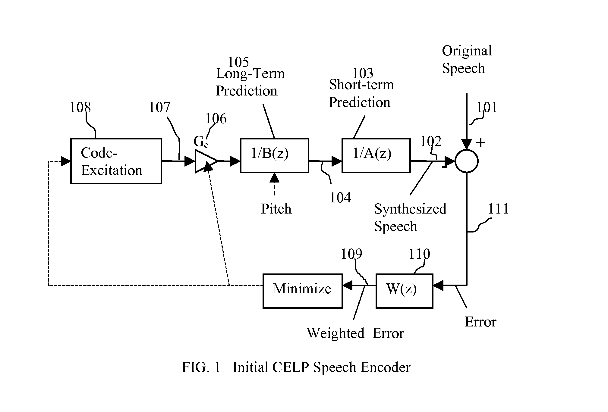
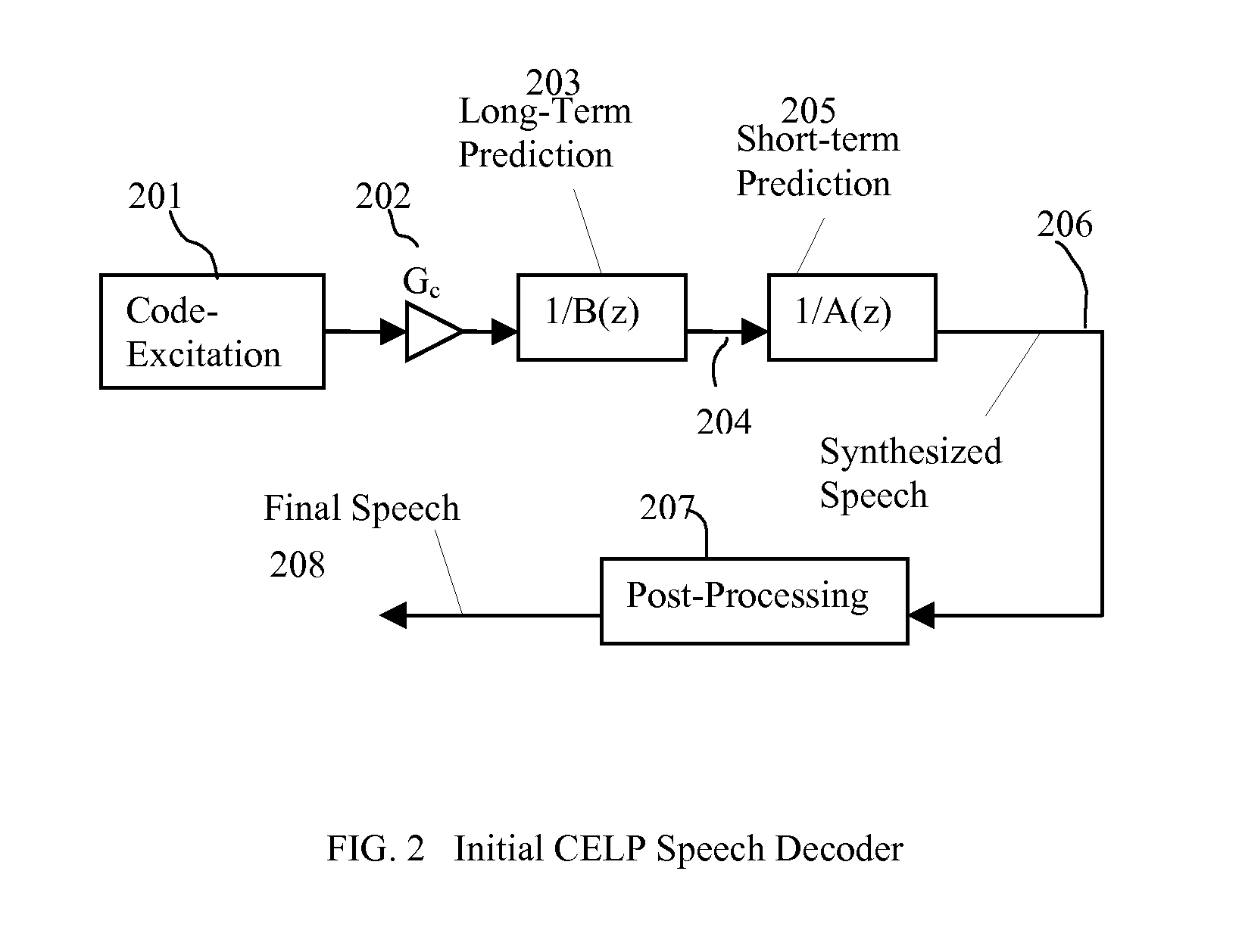
[0021]The present invention discloses a switched long-term pitch prediction approach which improves packet loss concealment. The following description contains specific information pertaining to the Code Excited Linear Prediction Technique (CELP). However, one skilled in the art will recognize that the present invention may be practiced in conjunction with various speech coding algorithms different from those specifically discussed in the present application. Moreover, some of the specific details, which are within the knowledge of a person of ordinary skill in the art, are not discussed to avoid obscuring the present invention.

[0022]The drawings in the present application and their accompanying detailed description are directed to merely example embodiments of the invention. To maintain brevity, other embodiments of the invention which use the principles of the present invention are not specifically described in the present application and are not specifically illustrated by the pr...


PUM


Abstract

A method of significantly reducing error propagation due to voice packet loss, while still greatly profiting from long-term pitch prediction, is achieved by adaptively limiting the maximum value of the pitch gain for the first pitch cycle within one frame. A speech coding system for encoding a speech signal, wherein said a plurality of speech frames are classified into said a plurality of classes depending on if the first pitch cycle is included in one subframe or several subframes. The pitch gain is set to a value significantly smaller than 1 for the subframes covering first pitch cycle; wherein the pitch gain reduction is compensated by increasing the coded excitation codebook size or adding one more stage of excitation for the subframes covering the first pitch cycle.

Description

CROSS REFERENCE TO RELATED APPLICATIONSProvisional Application Number US60 / 877,172Provisional Application Number US60 / 877,173BACKGROUND OF THE INVENTION[0001]1. Field of the Invention[0002]The present invention is generally in the field of signal coding. In particular, the present invention is in the field of speech coding and specifically in application where packet loss is an important issue during voice packet transmission.[0003]2. Background Art[0004]Traditionally, all parametric speech coding methods make use of the redundancy inherent in the speech signal to reduce the amount of information that must be sent and to estimate the parameters of speech samples of a signal at short intervals. This redundancy primarily arises from the repetition of speech wave shapes at a quasi-periodic rate, and the slow changing spectral envelop of speech signal.[0005]The redundancy of speech wave forms may be considered with respect to several different types of speech signal, such as voiced and ...

Claims


Application Information

Patent Timeline
Patent Type & Authority Applications(United States)
IPC IPC(8): G10L19/12
CPCG10L19/005G10L19/09G10L19/083
Inventor GAO, YANG
Owner HUAWEI TECH CO LTD
Learn More