
Hole-Injecting Material, Material for Light-Emitting Element, Light-Emitting Element, Organic Compound, Monomer, and Monomer Mixture

a technology of light-emitting elements and material, applied in the field of hole-injection materials, can solve the problems of difficult to say, poor reliability of manufactured products, and extremely poisonous antimony, and achieve the effects of reducing cost, favorable characteristics, and high usability of materials

Inactive Publication Date: 2008-06-26
SEMICON ENERGY LAB CO LTD
View PDF17 Cites 12 Cited by
  • Summary
  • Abstract
  • Description
  • Claims
  • Application Information

AI Technical Summary

Benefits of technology

[0012]Further, it is another object of the present invention to provide a high molecular weight material for a light-emitting element or a hole injecting high molecular weight material which has a sufficient hole injecting property, without using a dopant having an electron accepting property.
[0014]Furthermore, it is another object of the present invention to provide a material for a light-emitting element or a hole injecting material which has a sufficient hole injecting property and which can suppress defects of pixels of a light-emitting element formed with the material, without using a dopant having an electron accepting property.
[0017]Further, it is another object of the present invention to provide a light-emitting element with few incipient defects, which can be driven at a low voltage.
[0038]In addition, by using a hole injecting material of the present invention, a material for a light-emitting element or a hole injecting material for which a film-formation method having a high usability of materials can be used, in addition to the above effects.
[0039]A light-emitting element of the present invention which is manufactured using a hole injecting material of the present invention is a light-emitting element with favorable characteristics which can be formed at reduced cost, since a manufacturing method of a droplet discharging method or the like typified by an inkjet method which provides a good usability of materials can be used in forming a hole injecting layer.

Problems solved by technology

The acid component and antimony halide are not preferable industrially, since the former has a possibility of corrosion of an element electrode and causes poor reliability of manufactured products and the latter employs antimony which is extremely poisonous.
However, it is difficult to say that the material of Reference 3 has a sufficient hole injecting property, since a voltage of as high as 28V is needed for driving a light-emitting element formed using the material.

Method used


Image

  • Hole-Injecting Material, Material for Light-Emitting Element, Light-Emitting Element, Organic Compound, Monomer, and Monomer Mixture
  • Hole-Injecting Material, Material for Light-Emitting Element, Light-Emitting Element, Organic Compound, Monomer, and Monomer Mixture
  • Hole-Injecting Material, Material for Light-Emitting Element, Light-Emitting Element, Organic Compound, Monomer, and Monomer Mixture

Examples


embodiment mode 1

[0059]One mode of the present invention will be described.

[0060]A hole injecting material of the present invention is a polymer having a repeating unit represented by the following general formula (1). In the formula (1), R1 represents hydrogen, an alkyl group, a cyano group, or an alkoxy group, and R2 represents an aryl group. In the polymer with such a structure, a polymer having ionization potential of 4.9 eV or more and 5.4 eV or less is a polymer which can accept holes smoothly from a metal, and can be used favorably as a hole injecting material.

[0061]In the general formula, the aryl group represented by R2 preferably has an electron donating substituent, and it is preferable that the electron donating substituent has a substituent constant value σ of −2.1 or more and 0.15 or less in Hammett rule. This is because it can be favorably used as a hole injecting material in this case without using an electron donating dopant.

[0062]The aryl group represented by R2 of the general form...

embodiment mode 2

[0075]As one mode of the present invention, an organic compound of a monomer of the present invention which is used for synthesizing a hole injecting material of the present invention, as shown in Embodiment Mode 1, will be described.

[0076]A monomer of the present invention is an organic compound represented by the following general formula (4). In the formula, Ar1 to Ar3 individually represent an aryl group having 6 to 14 carbon atoms, and the aryl group may be substituted or unsubstituted. In addition, Ar2 and Ar3 may condense with each other.

[0077]By polymerizing the organic compound represented by the above general formula (4), a hole injecting material of a polymer can be synthesized, which is one mode of the present invention and is represented by the following general formula (1).

[0078]However, in the formula, R1 represents hydrogen, an alkyl group, a cyano group, or an alkoxy group, and R2 represents a group represented by the general formula (2).

[0079]In the above formula, ...

embodiment mode 3

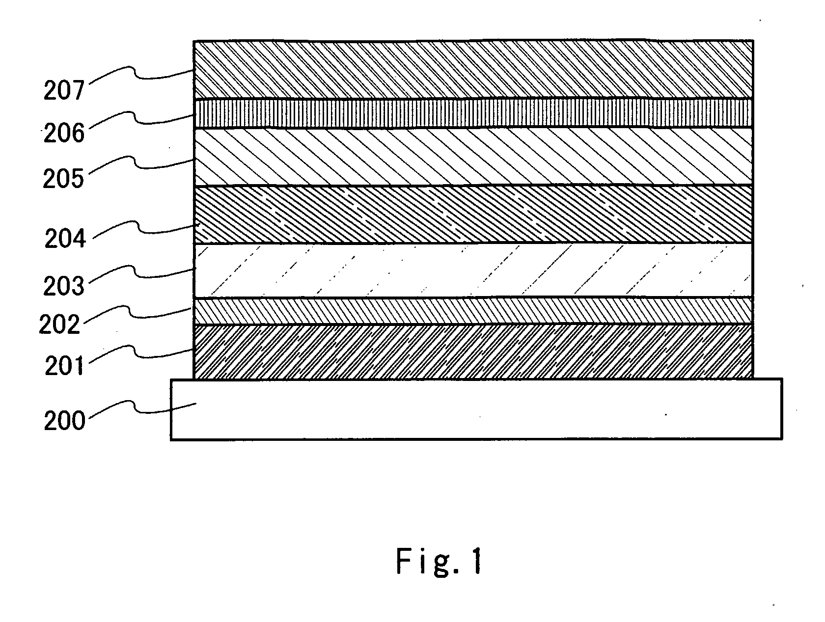
[0082]A light-emitting element of the present invention will be described as one mode of the present invention. FIG. 1 shows a structure of the light-emitting element of the present invention as one example.

[0083]A hole injecting layer in the light-emitting element of the present invention is formed by a hole injecting material of a polymer having a repeating unit represented by the following general formula (1). In the formula (1), R1 represents hydrogen, an alkyl group, a cyano group, or an alkoxy group, and R2 represents any one of groups represented by the following general formula (2).

[0084]In the above formula, Ar1 to Ar3 individually represent an aryl group having 6 to 14 carbon atoms, and the aryl group may be substituted or unsubstituted. In addition, Ar1 and Ar2 may condense with each other.

[0085]The mode of the light-emitting element using a hole injecting material of the present invention as a hole injecting layer will be described with reference to FIG. 1.

[0086]FIG. 1 s...


PUM

PropertyMeasurementUnit
ionization potentialaaaaaaaaaa
voltageaaaaaaaaaa

Abstract

An object of the present invention to provide a material for a light-emitting element or a hole injecting high molecular weight material which has a sufficient hole injecting property, without using a dopant having an electron accepting property. One of materials of the present invention which can achieve the object, has a repeating unit represented by the following formula (1), In the formula (1), R1 represents hydrogen, an alkyl group, a cyano group, or an alkoxy group, and R2 represents an aryl group. The material has an ionization potential of 4.9 eV or more and 5.4 eV or less.

Description

TECHNICAL FIELD[0001]The present invention relates to materials for light-emitting elements which can emit light by allowing current to flow thereto, in particular, a material having a hole injecting property, and further, a high molecular weight compound material, (also referred to as polymer) having a hole injecting property for light-emitting elements.[0002]In recent years, a light-emitting device or a display using a light-emitting element formed with an organic material has been actively developed. The light-emitting element is manufactured by sandwiching an organic compound between a pair of electrodes. Unlike a liquid crystal display device, the light-emitting element itself emits light and does not require a light source such as a backlight. In addition, the element itself is very thin. Therefore, the light-emitting element is very advantageous in manufacturing a thin lightweight display.[0003]In a light-emitting mechanism of the light-emitting element, it is said that elect...

Claims


Application Information

Patent Timeline
Patent Type & Authority Applications(United States)
IPC IPC(8): C08F12/32C07C211/54
CPCC07C211/54C08F112/32H01L51/004H01L51/0052H01L51/0059H01L51/5088H01L51/0062H01L51/5048C08F4/04H10K85/141H10K85/649H10K85/631H10K85/615H10K50/14H10K50/17C09K19/3895C09K2200/0642
Inventor SUZUKI, TSUNENORINOMURA, RYOJIKAWAKAMI, SACHIKO
Owner SEMICON ENERGY LAB CO LTD
Learn More