
Fuel cell system

a fuel cell and household technology, applied in the direction of fuel cells, dc network circuit arrangements, electrochemical generators, etc., can solve the problems of low fuel cell power utilization rate, excessive power generation, and fuel cell power not being able to follow a drastic variation in load, so as to improve the capacity operating rate of the fuel cell, improve the rate of generated-power utilization rate, and improve the reliability

Inactive Publication Date: 2008-06-26
ORMON CORP
View PDF3 Cites 7 Cited by
  • Summary
  • Abstract
  • Description
  • Claims
  • Application Information

AI Technical Summary

Benefits of technology

[0017]In accordance with the fuel cell system of the present invention, an excessive power is charged to a capacitor, and upon insufficiency in the cell power, the accumulated power of the capacitor is discharged so as to compensate for the insufficient power. Thus, a superior follow-up property to load variations is provided and a self-sustaining operation is positively ensured without using a heater so that the rate of fuel cell power utilization is improved. As a result, the system is effectively suitable for use in a local place where no commercial power supply is available as well as for use as an emergency power supply at the time of commercial power supply service interruption.
[0018]Moreover, at the time of the low load operation, the output power of the fuel cell is limited in response to a voltage rise of the capacitor so that the excessive power can be positively charged to the capacitor by allowing the capacitor to have a space capacity for charging. Thus, the capacity operating rate of the fuel cell is improved, and the system enables to positively prevent a reversed current from flowing into the commercial power supply.
[0019]Furthermore, at the time of the low load operation, the output power of the fuel cell is limited in response to a voltage rise of the capacitor so that the system enables to prevent the capacitor from deteriorating and consequently to positively control the capacitor voltage to be maintained within an applicable range by limiting the charging voltage of the capacitor so as not to exceed the withstand voltage thereof, thereby making it possible to provide superior reliability. Since the output power PB of the fuel cell and the voltage VC of the capacitor are made to satisfy the above-mentioned relationship, the fuel cell is allowed to power-generate the highest possible output of the fuel cell so that the rate of generated-power utilization of the fuel cell is improved.
[0020]At the time of the high load operation, the output of the power conditioner is limited in response to a voltage drop of a capacitor so as not to allow the discharging voltage of the capacitor to reach a discharge depth or less, thereby making it possible to prevent the capacitor from deteriorating.
[0022]In accordance with this fuel cell system, since the output power of the fuel cell is raised in response to a voltage drop of the capacitor, the fuel cell is allowed to positively generate power when a space capacity is available in the capacitor so that the power is accumulated in the capacitor. In contrast, by raising the output of the power conditioner in response to a voltage rise of the capacitor, the power having been accumulated in the capacitor is positively discharged to the load. In this manner, when a space capacity is available in the capacitor, the accumulated power is positively discharged to the load to be utilized so that the power generating coefficient of the fuel cell is enhanced, and the fuel cell having a rated output smaller than the rated output of the power conditioner can be utilized.
[0023]According to the present invention, it becomes possible to provide a fuel cell system which has a superior follow-up property in response to variations in load, prevents the built-in capacitor from deteriorating, as well as positively preventing a reversed current from flowing into the commercial power supply, and improves the capacity operating rate of the fuel cell.

Problems solved by technology

This fuel cell system does not permit the fuel cell power to exceed a specified value and reversely flow into the commercial power supply, and in addition, the fuel cell power is not operative to follow a drastic variation in the load.
For this reason, when the load is varied to a low level, an excessive power is generated due to a slow follow-up operation in following the variation.
In this fuel cell system, however, because the rate of fuel cell power utilization is low due to a slow follow-up property to a drastic variation in the load, the installation rate of this system for practical use is low.
In the fuel cell system in which the charging / discharging device utilizing a capacitor is assembled however, a problem arises in that, when a capacitor is over-charged to a level exceeding the capacitor withstand voltage (the upper limit value of capacitor voltage) or when a capacitor is over-discharged down to a capacitor discharge depth (the lower limit value of capacitor voltage) or less, the charging / discharging means might be damaged to deteriorate the capacitor.

Method used


Image

  • Fuel cell system
  • Fuel cell system
  • Fuel cell system

Examples


Embodiment Construction

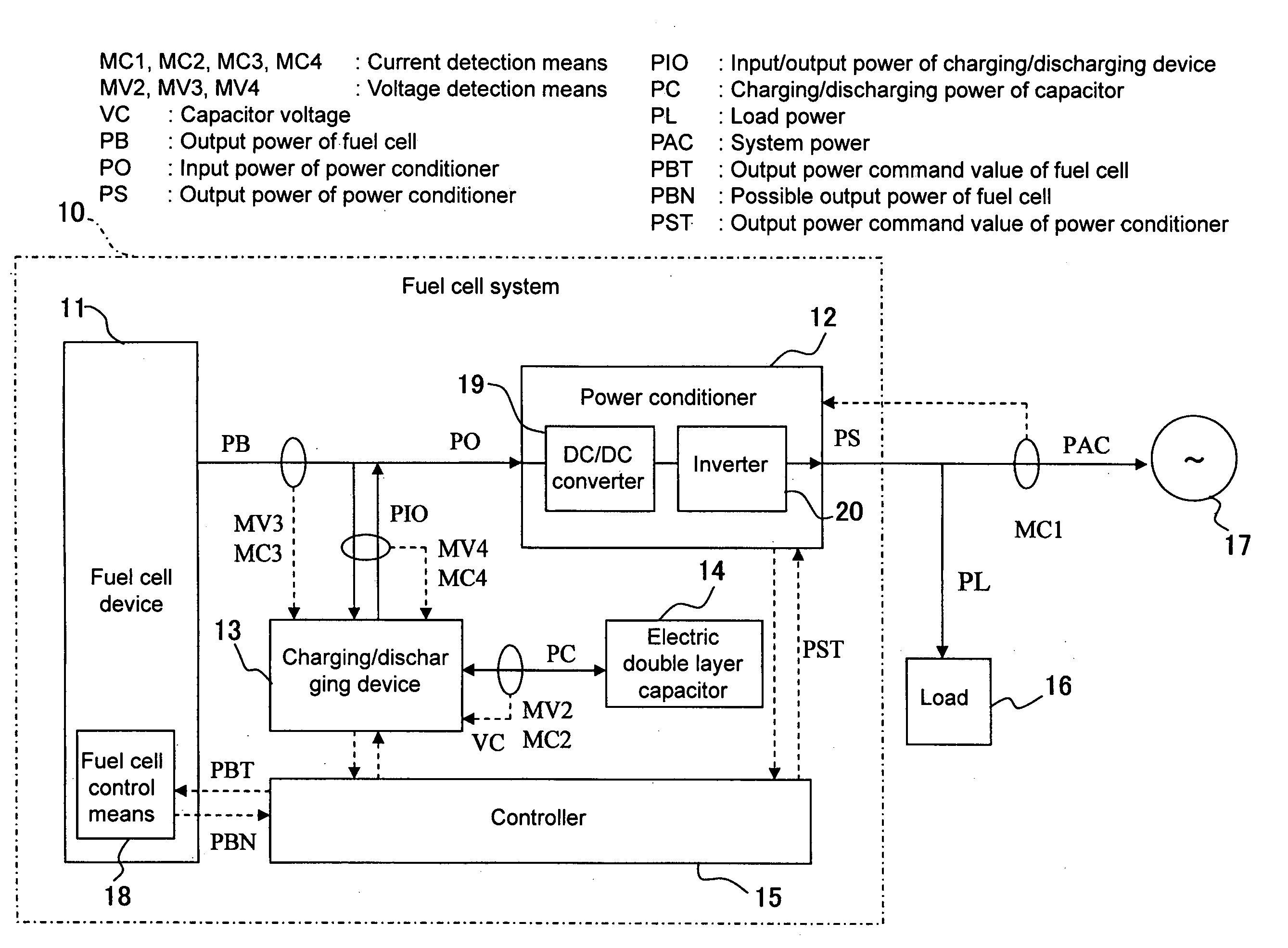
[0032]Referring to drawings, the following description will discuss a fuel cell system in accordance with an Embodiment of the present invention. Here, although the power conversion between a charging / discharging device and a power conditioner (including built-in DC / DC converter and inverter) actually causes a loss, the loss is ignored for simplicity of explanation, and the explanation is given supposing that the input and output powers of the charging / discharging device are equal to each other (PIO=PC) and that the input and output powers of the power conditioner are also equal to each other (PO=PS).

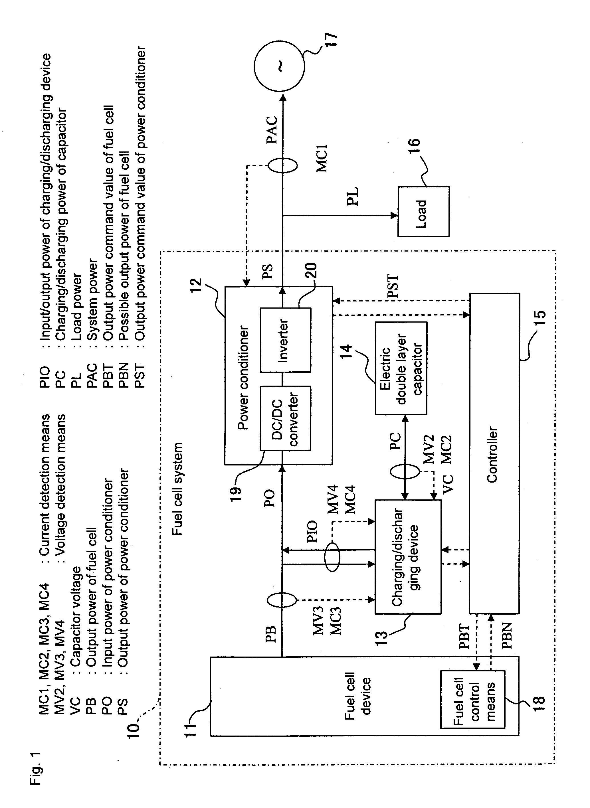
[0033]FIG. 1 shows a schematic structure of a fuel cell system 10 including a fuel cell device 11, a power conditioner 12, a charging / discharging device 13, an electric double layer capacitor 14, a controller 15, a load 16 and a commercial power supply 17 (system).

[0034]The fuel cell device 11, which supplies a DC output (cell power) from the fuel cell, is provided with, for example, a ...


PUM

PropertyMeasurementUnit
poweraaaaaaaaaa
power consumptionaaaaaaaaaa
voltageaaaaaaaaaa

Abstract

The fuel cell system includes a fuel cell; a power conditioner that converts a cell power supplied from the fuel cell to a power corresponding to a load; a capacitor to which an excessive output power of the fuel cell is charged at the time of a low load operation and from which a power corresponding to the insufficient output power of the fuel cell is discharged at the time of a high load operation; a voltage detection means for detecting a voltage of the capacitor; and a control means that determines the low load operation or the high load operation, calculates an output power from the fuel cell to maintain the excessive power generated at the time of the low load operation within a space capacity of the capacitor, and controls the output power of the fuel cell not to exceed the calculated value.

Description

BACKGROUND OF THE INVENTION[0001]This application claims priority from Japanese Patent Application P2006-337188, filed on Dec. 14, 2006. The entire contents of the aforementioned application is incorporated herein by reference.[0002]1. Field of the Invention[0003]The present invention relates to a household fuel cell system using a fuel cell. The fuel cell is provided with not a structure in which hydrogen and oxygen are directly burned, but a structure in which they are allowed to separately electrochemically react in a fuel electrode and an air electrode separated by an electrolyte, so that electricity is generated by taking out electrons to an external circuit.[0004]2. Description of the Related Art[0005]With respect to the fuel cell system, such a system has been proposed in which the fuel cell output is made coincident with the load power (power consumed by a load) so as to prevent a current from reversely flowing into the commercial power supply (refer to, for example, Japanes...

Claims


Application Information

Patent Timeline
Patent Type & Authority Applications(United States)
IPC IPC(8): H01M8/04
CPCH02J2001/004H02J3/387H02J2300/30H02J3/381Y02E60/50H01M8/04
Inventor MURABAYASHI, HARUYASU
Owner ORMON CORP
Learn More