
Carbon nanotubes for transfer belt applications

Inactive Publication Date: 2008-06-26
XEROX CORP
View PDF2 Cites 23 Cited by
  • Summary
  • Abstract
  • Description
  • Claims
  • Application Information

AI Technical Summary

Benefits of technology

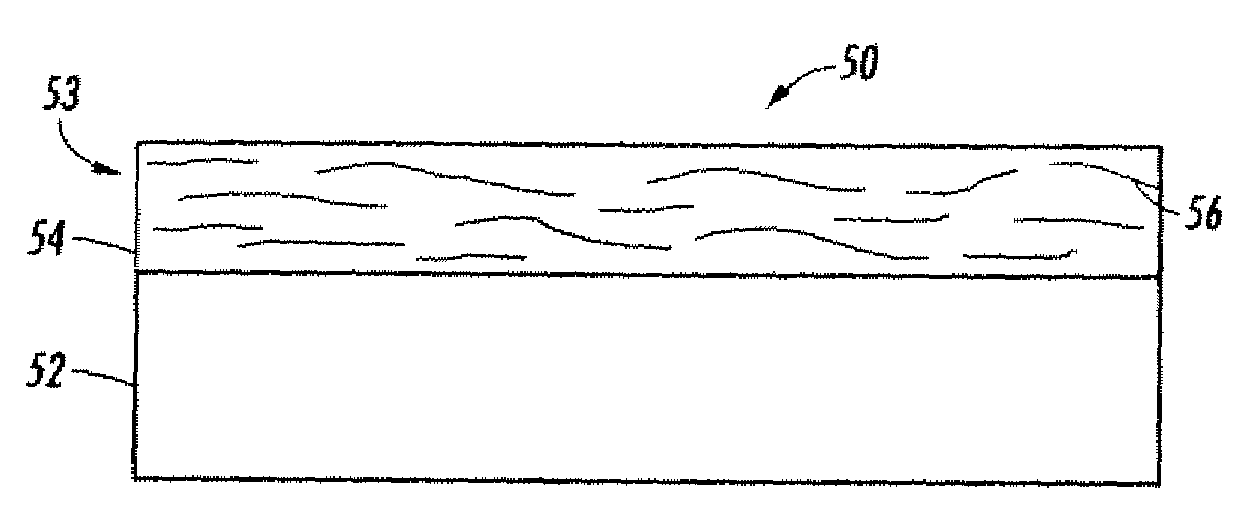
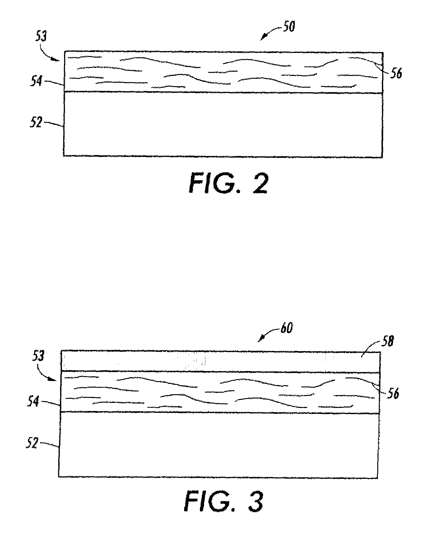
[0036]A further embodiment may include adding a cross-linking agent to the suspension prior to coating. In another embodiment the conforman

Problems solved by technology

However, when a liquid developer material is employed, the copy sheet is wet with both the toner particles and the liquid carrier.
Although intermediate transfer members allow for positive attributes such as enabling high throughput at modest process speeds, improving registration of the final color toner image in color systems using synchronous development of one or more component colors using one or more transfer stations, and increasing the range of final substrates that can be used, a disadvantage of using all intermediate transfer member is that a plurality of transfer steps is required allowing for the possibility of charge exchange occurring between toner particles and the transfer member which ultimately leads to less than complete toner transfer.
The result is low resolution images on the image receiving substrate and image deterioration.
When the image is in color, the image additionally suffers from color shifting and color deterioration.
In addition, the use of charging agents in liquid developers, although providing good quality images and acceptable resolution due to improved charging of the toner, can exacerbate the problem of charge exchange between the toner and the intermediate transfer member.
While addition of electrically conductive additives to polymers may partially control the resistivity of polymer coatings or layers to some extent, there are problems associated with the use of these additives, such as problems with non-uniform dispersion.
In particular, particles frequently bloom or migrate to the surface of the poly % mer and cause an imperfection in the polymer.
This leads to a non-uniform resistivity, which in turn, leads to poor antistatic properties and poor mechanical strength.
Such carbon dispersions are difficult to prepare due to carbon gelling, and the resulting layers may deform due to gelatin formation.
This can lead to an adverse change in the conformability of the layer, which in turn, can lead to insufficient transfer and poor copy quality, and possible contamination of other machine parts and later copies.
However, the required tolerance in the filler loading to achieve the required range of resistivity is narrow.
This, along with the large “batch to batch” variation, leads to the need for extremely tight resistivity control.
In addition, carbon filled polymer surfaces have typically had very poor dielectric strength and sometimes significant resistivity dependence on applied fields.
This leads to a compromise in the choice of centerline resistivity due to the variability in the electrical properties, which in turn, ultimately leads to a compromise in performance.

Method used


Image

  • Carbon nanotubes for transfer belt applications
  • Carbon nanotubes for transfer belt applications
  • Carbon nanotubes for transfer belt applications

Examples


Embodiment Construction

[0048]Before the present methods, systems and materials are described, it is to be understood that this disclosure is not limited to the particular methodologies, systems and materials described, as these may vary. It is also to be understood that the terminology used in the description is for the purpose of describing the particular versions or embodiments only, and is not intended to limit the scope. For example, as used herein and in the appended claims, the singular forms “a,”“an,” and “the” include plural references unless the context clearly dictates otherwise. In addition, the word “comprising” as used herein is intended to mean “including but not limited to.” Unless defined otherwise, all technical and scientific terms used herein have the same meanings as commonly understood by one of ordinary skill in the art.

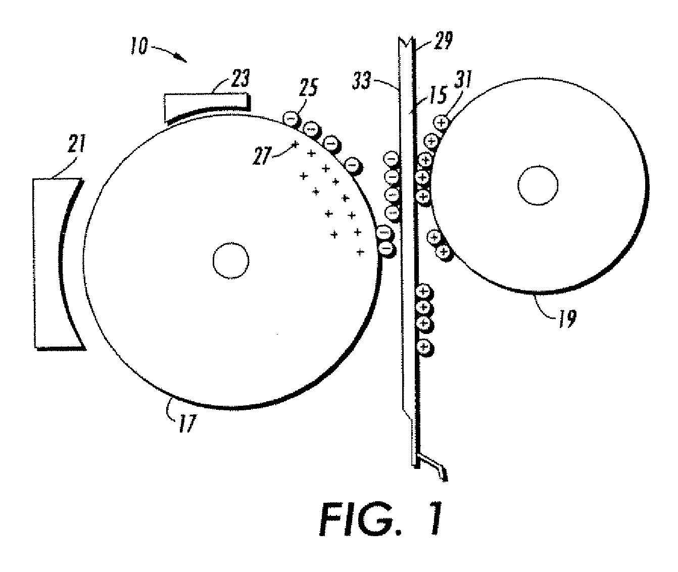
[0049]Referring to FIG. 1, an embodiment herein includes an image development system 10 having an intermediate transfer member 15. The intermediate transfer member 15...


PUM


Abstract

A xerographic transfer member includes a resistive, electrically relaxable, polyimide substrate, and a conformance resistive layer that includes a fluoroelastomer composite. The fluoroelastomer composite includes a cross-linked fluoropolymer, a plurality of carbon nanotubes, and exhibits a resistivity from about 107 ohm-cm to about 1013 ohm-cm.

Description

CROSS-REFERENCE TO RELATED APPLICATIONS[0001]Not applicable.STATEMENT REGARDING FEDERALLY SPONSORED RESEARCH[0002]Not applicable.NAMES OF PARTIES TO A JOINT RESEARCH AGREEMENT[0003]Not applicable.SEQUENCE LISTING[0004]Not applicable.BACKGROUND[0005]1. Technical Field[0006]This disclosure relates to electrically conductive coatings and processes for their preparation. The disclosure relates to processes for producing electrically conductive coatings useful for components for electrical applications, especially electrostatographic applications such as xerographic applications. Specifically, this disclosure relates to intermediate transfer components that are useful in transferring a developed image in an electrostatographic, especially xerographic machine or apparatus.[0007]2. Description of the Related Art[0008]In a typical electrostatographic reproducing apparatus, a light image of an original to be copied is recorded in the form of an electrostatic latent image upon a photosensitiv...

Claims


Application Information

Patent Timeline
IPC IPC(8): B32B5/16B05D3/02
CPCB82Y30/00G03G2215/1623Y10T428/269Y10T428/25G03G15/162Y10T428/3154Y10T428/31544
Inventor LAW, KOCK-YEE
Owner XEROX CORP
Learn More