
System and method for synchronizing a viewing device

Active Publication Date: 2008-06-26
TEXAS INSTR INC
View PDF11 Cites 45 Cited by
  • Summary
  • Abstract
  • Description
  • Claims
  • Application Information

AI Technical Summary

Benefits of technology

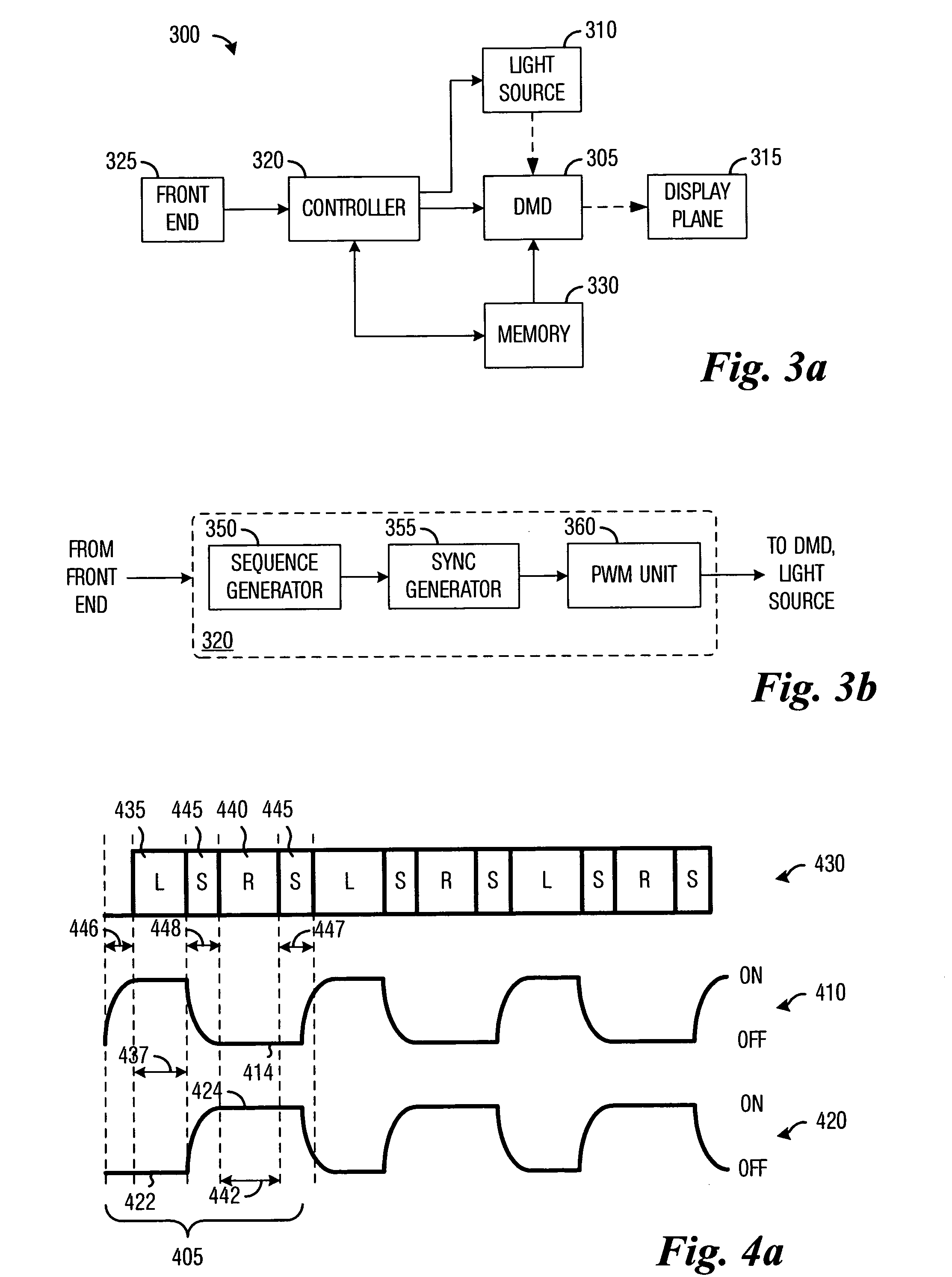
[0010]An advantage of an embodiment is the elimination of a dedicated synchronization emitter, which typically is an external device coupled to a projection display system. The elimination of the dedicated synchronization emitter may reduce the component count of the projection display system, which may help keep the costs of the projection display system to a minimum. Furthermore, a reduction in the number of components may increase product reliability since there are fewer components that may fail.
[0011]A further advantage of an embodiment is that existing projection display system hardware is sufficient. Therefore the capability of displaying three-dimensional images and / or dual images using standard projection display system hardware will require only a small development and cost investment.

Problems solved by technology

This is unfortunate since three-dimensional images may convey a large amount of information and three-dimensional images and video may enhance the viewers' enjoyment.

Method used


Image

  • System and method for synchronizing a viewing device
  • System and method for synchronizing a viewing device
  • System and method for synchronizing a viewing device

Examples


Embodiment Construction

[0019]The making and using of the embodiments are discussed in detail below. It should be appreciated, however, that the present invention provides many applicable inventive concepts that can be embodied in a wide variety of specific contexts. The specific embodiments discussed are merely illustrative of specific ways to make and use the invention, and do not limit the scope of the invention.

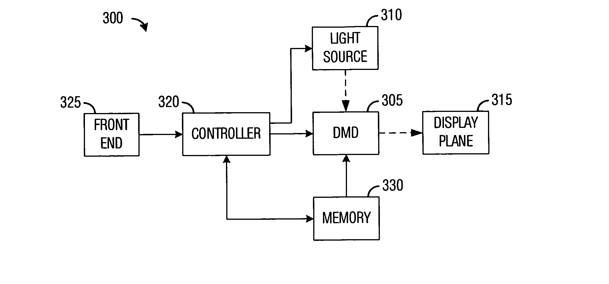
[0020]The embodiments will be described in a specific context, namely a DMD-based projection display system. The invention may also be applied, however, to other microdisplay-based projection display systems, such as projection display systems utilizing deformable micromirrors, transmissive and reflective liquid crystal, liquid crystal on silicon, and so forth, microdisplays.

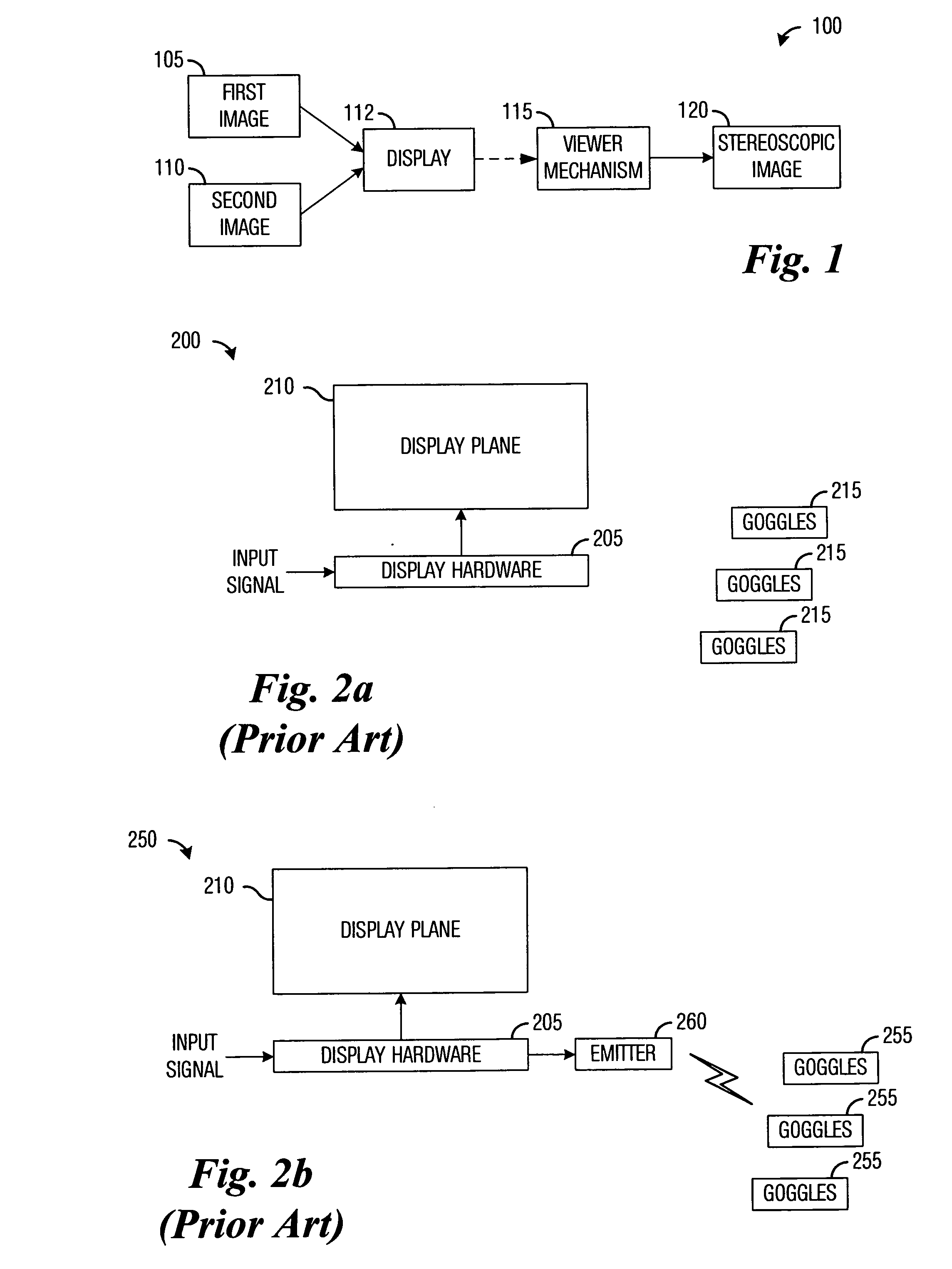
[0021]With reference now to FIG. 1, there is shown a diagram of a stereoscopic image display system 100. The stereoscopic image display system 100 includes a display 112 that may be used to display a first image 105 and a se...


PUM


Abstract

System and method for synchronizing shutter glasses with a display system. An embodiment comprises displaying a first image from a first image stream on a display plane, displaying a second image from a second image stream on the display plane, and displaying a synchronization signal on the display plane, during a first, a second, and a third display period, respectively. The first image and the second image are displayed at least partially on the same area of the display plane and the first and the second display periods do not overlap. The display of the synchronization signal on the display plane enables the elimination of a dedicated synchronization signal broadcast unit, thereby reducing the cost while increasing the reliability of a display system.

Description

TECHNICAL FIELD[0001]The present invention relates generally to a system and method for displaying images, and more particularly to a system and method for synchronizing shutter glasses with a display system.BACKGROUND[0002]Standard televisions and projection display systems display two dimensional images. Images of three-dimensional objects and scenes are flattened to two-dimensions when the images are recorded and the resulting two-dimensional images are displayed without regaining any of the three-dimensional information. This is unfortunate since three-dimensional images may convey a large amount of information and three-dimensional images and video may enhance the viewers' enjoyment.[0003]It may be possible to recreate three-dimensional images from two two-dimensional images with each two-dimensional image being a recording of a three-dimensional scene taken with slightly different perspectives. When the two two-dimensional images are displayed, each two-dimensional image being...

Claims


Application Information

Patent Timeline
IPC IPC(8): H04N9/44H04N5/74H04N13/398H04N13/363
CPCG09G3/003H04N13/0497H04N13/0459H04N13/0438H04N13/341H04N13/363H04N13/398
Inventor BASILE, GREGORY RAYMONDPORADISH, FRANK JOSEPH
Owner TEXAS INSTR INC
Learn More