
Multiple deposition for integration of spacers in pitch multiplication process

a multiplication process and spacer technology, applied in the field of masking techniques, can solve the problems of reducing the size of features, and reducing the minimum pitch of a particular photolithographic techniqu

Inactive Publication Date: 2008-06-26
ROUND ROCK RES LLC
View PDF99 Cites 295 Cited by
  • Summary
  • Abstract
  • Description
  • Claims
  • Application Information

AI Technical Summary

Benefits of technology

[0016]According to yet another aspect of the invention, a method is provided for forming an integrated circuit. The method comprises forming a mandrel over a substrate. A first spacer layer is deposited over the mandrel by a

Problems solved by technology

However, due to factors such as optics and light or radiation wavelength, photolithography techniques each have a resolution limit that results in a minimum pitch below which a particular photolithographic technique cannot reliably form features.
Thus, the minimum pitch of a photolithographic technique is an obstacle to continued feature size reduction.

Method used


Image

  • Multiple deposition for integration of spacers in pitch multiplication process
  • Multiple deposition for integration of spacers in pitch multiplication process
  • Multiple deposition for integration of spacers in pitch multiplication process

Examples


Embodiment Construction

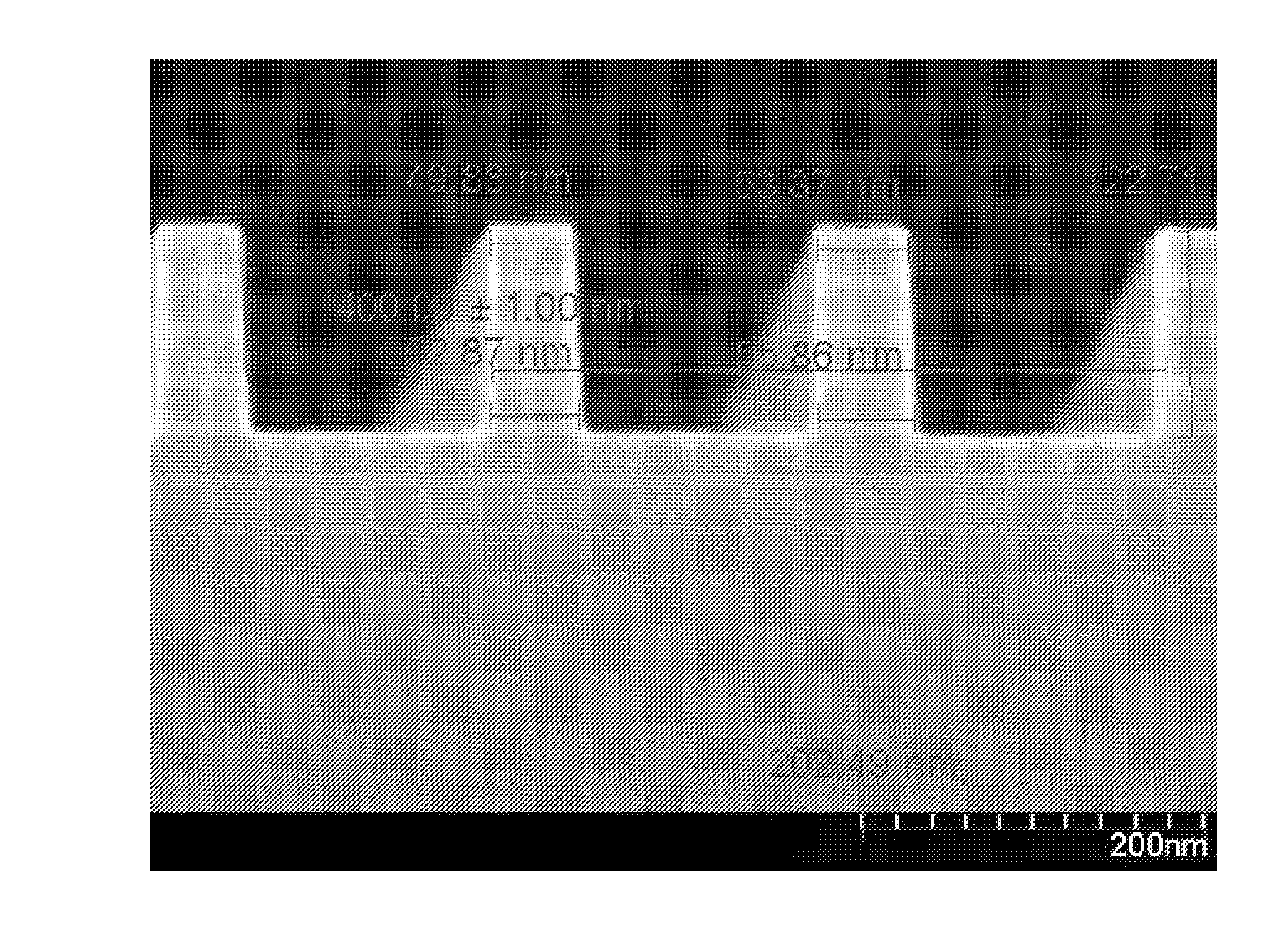
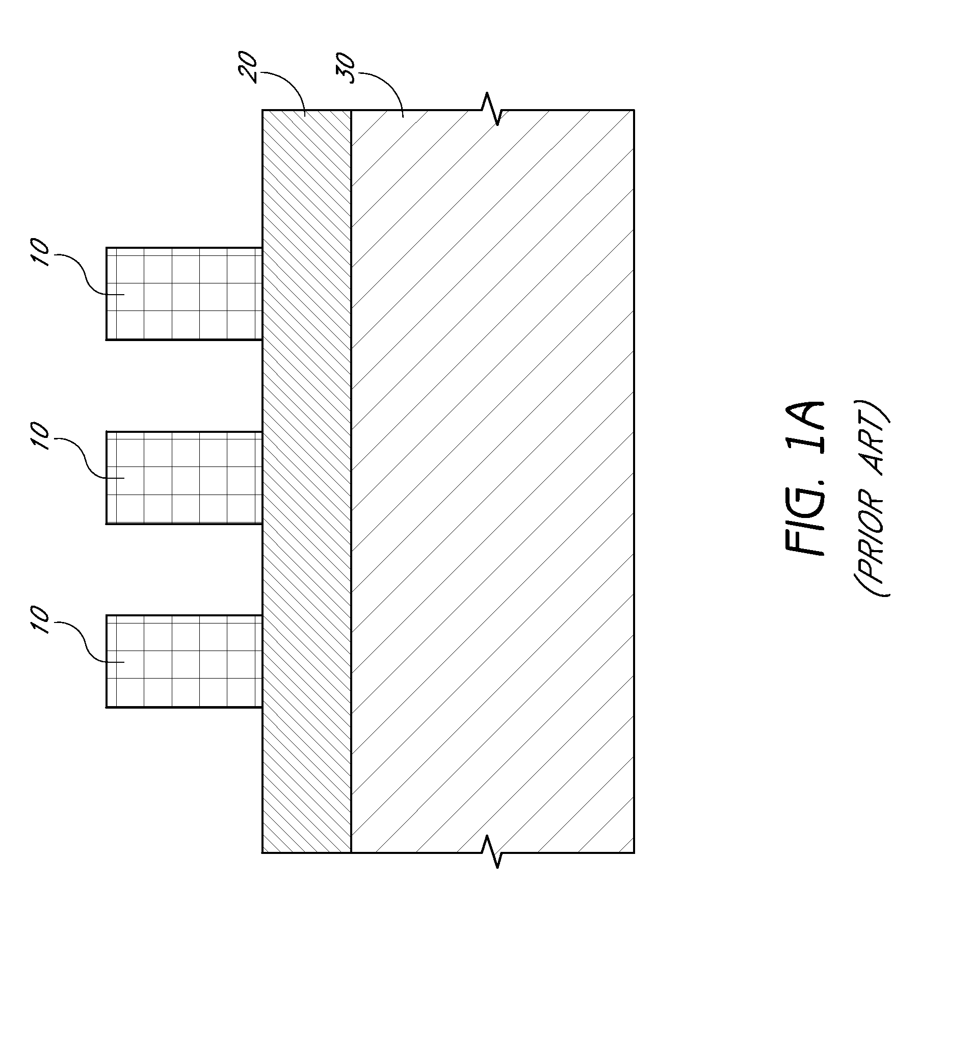
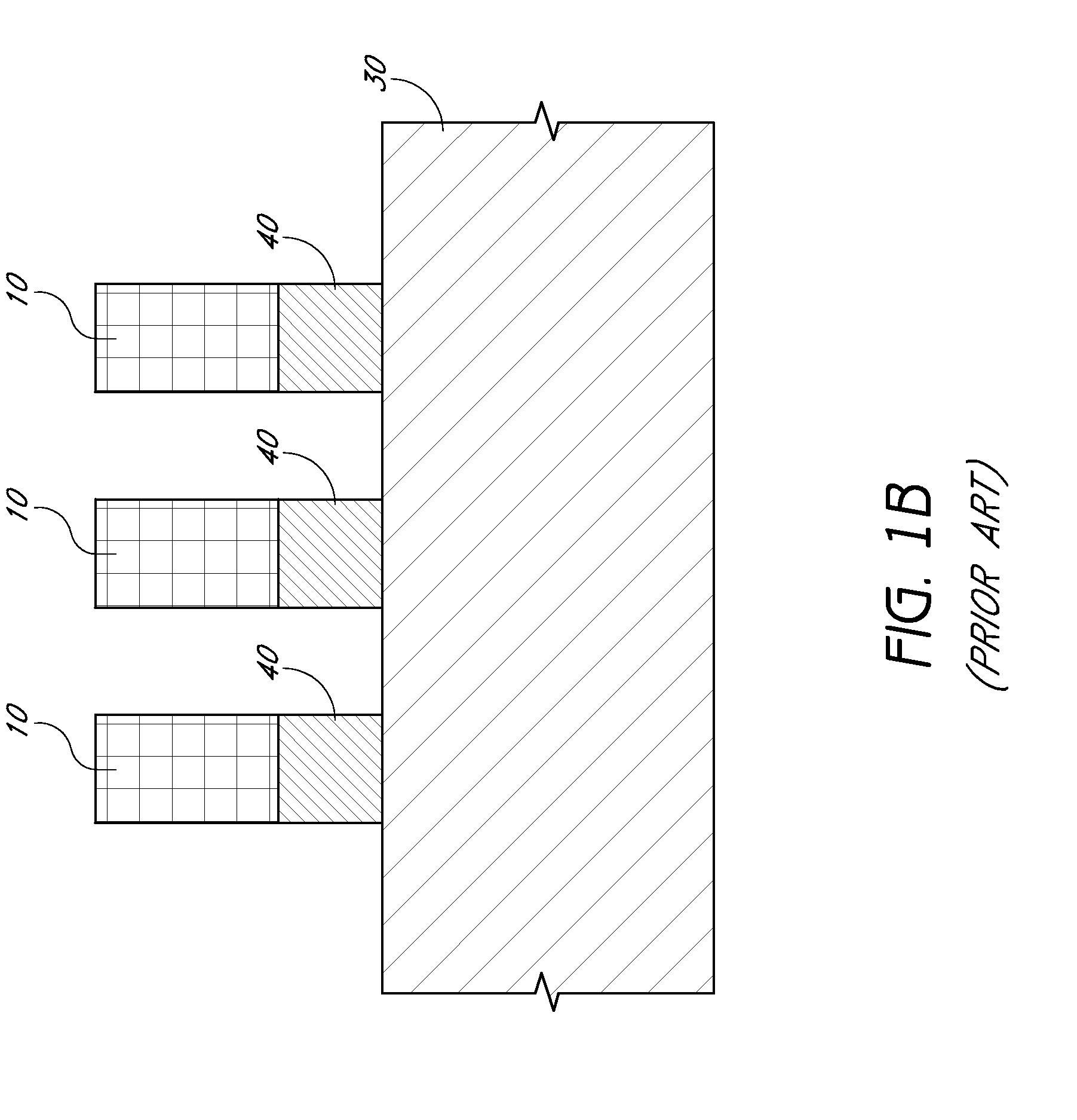
[0038]It has been found that mandrels can be deformed during the deposition of spacer material. FIG. 2A shows mandrels before depositing spacer material. Where the mandrels are formed of amorphous carbon, silicon oxide can be used as a spacer material, among other materials possibilities. The spacer material is preferably deposited using a process that deposits highly conformal layers, e.g., processes such as thermal chemical vapor deposition of silicon oxide using O3 and TEOS. O3, however, is a strong oxidizer and has been found to shrink and otherwise deform the amorphous carbon mandrels, as shown in FIG. 2B. Consequently, spacers formed on the deformed mandrels may no longer be at their expected and desired positions and / or spacings from one another. As a result, the predictability and uniformity of spacer location and spacing can be adversely affected by mandrel deformation.

[0039]In preferred embodiments of the invention, in a process for minimizing mandrel deformation, a layer ...


PUM

PropertyMeasurementUnit
Densityaaaaaaaaaa
Ratioaaaaaaaaaa
Electrical conductoraaaaaaaaaa

Abstract

Pitch multiplication is performed using a two step process to deposit spacer material on mandrels. The precursors of the first step react minimally with the mandrels, forming a barrier layer against chemical reactions for the deposition process of the second step, which uses precursors more reactive with the mandrels. Where the mandrels are formed of amorphous carbon and the spacer material is silicon oxide, the silicon oxide is first deposited by a plasma enhanced deposition process and then by a thermal chemical vapor deposition process. Oxygen gas and plasma-enhanced tetraethylorthosilicate (TEOS) are used as reactants in the plasma enhanced process, while ozone and TEOS are used as reactants in the thermal chemical vapor deposition process. The oxygen gas is less reactive with the amorphous carbon than ozone, thereby minimizing deformation of the mandrels caused by oxidation of the amorphous carbon.

Description

REFERENCE TO RELATED APPLICATIONS[0001]This application is a continuation of U.S. patent application Ser. No. 11 / 213,486 to Bai, filed Aug. 25, 2005.[0002]This application is also related to the following: U.S. patent application Ser. No. 10 / 934,778 to Abatchev et al., filed Sep. 2, 2004; and U.S. Patent Provisional Application No. 60 / 662,323 to Tran et al., filed Mar. 15, 2005, entitled Pitch Reduced Patterns Relative To Photolithography Features.BACKGROUND OF THE INVENTION[0003]1. Field of the Invention[0004]This invention relates generally to integrated circuit fabrication and, more particularly, to masking techniques.[0005]2. Description of the Related Art[0006]As a consequence of many factors, including demand for increased portability, computing power, memory capacity and energy efficiency, integrated circuits are continuously being reduced in size. The sizes of the constituent features that form the integrated circuits, e.g., electrical devices and interconnect lines, are als...

Claims


Application Information

Patent Timeline
IPC IPC(8): B44C1/22
CPCH01L21/02164H01L21/022H01L21/02271H01L21/31612H01L21/0337H01L21/0338H01L21/02274H01L21/0228
Inventor BAI, JINGYISANDHU, GURTEJ S.MENG, SHUANG
Owner ROUND ROCK RES LLC
Learn More