
Method for preparing an electrokinetic element

a technology of electrokinetic elements and electrokinetic elements, which is applied in the direction of electrolysis, diaphragms, isotope separation, etc., can solve the problems of increasing the complexity and cost of the process, and the difficulty of controlling the lamination process

Inactive Publication Date: 2008-06-26
LIFESCAN IP HLDG LLC
View PDF2 Cites 97 Cited by
  • Summary
  • Abstract
  • Description
  • Claims
  • Application Information

AI Technical Summary

Problems solved by technology

There are various drawbacks to this technique.
In addition, several layers of adhesive must be used, increasing the complexity and cost of the process.
The quality of the adhesive bond also depends on time, temperature, pressure, and geometry, making the lamination process difficult to control.

Method used


Image

  • Method for preparing an electrokinetic element
  • Method for preparing an electrokinetic element
  • Method for preparing an electrokinetic element

Examples


Embodiment Construction

[0017]Certain exemplary embodiments will now be described to provide an overall understanding of the principles of the structure, function, manufacture, and use of the devices and methods disclosed herein. One or more examples of these embodiments are illustrated in the accompanying drawings. Those skilled in the art will understand that the devices and methods specifically described herein and illustrated in the accompanying drawings are non-limiting exemplary embodiments and that the scope of the present invention is defined solely by the claims. The features illustrated or described in connection with one exemplary embodiment may be combined with the features of other embodiments. Such modifications and variations are intended to be included within the scope of the present invention.

[0018]The features disclosed herein are applicable to a variety of electrokinetic infusion pump systems. For example, the methods disclosed herein can be used in the manufacture of electrokinetic infu...


PUM

PropertyMeasurementUnit
thicknessaaaaaaaaaa
diameteraaaaaaaaaa
diameteraaaaaaaaaa

Abstract

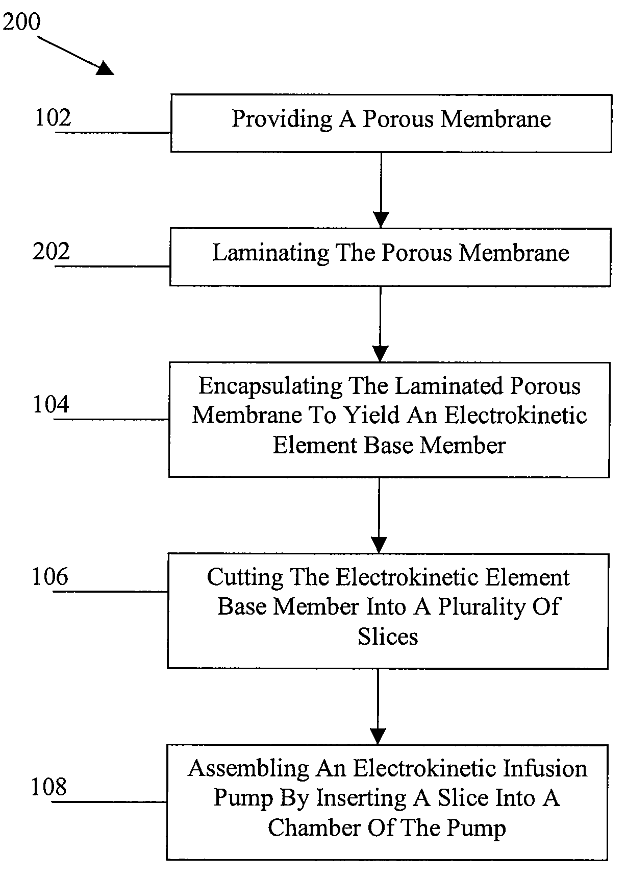
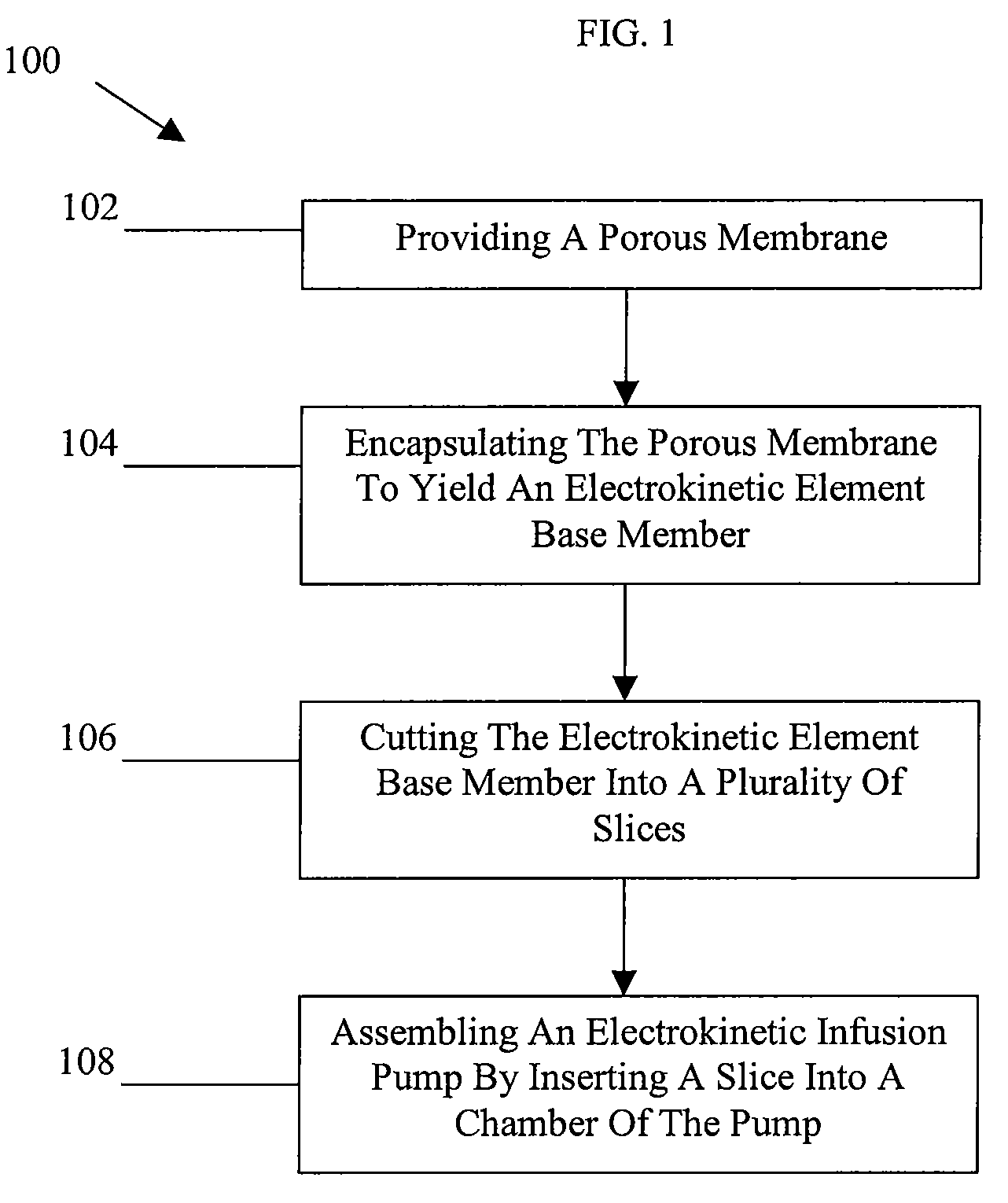
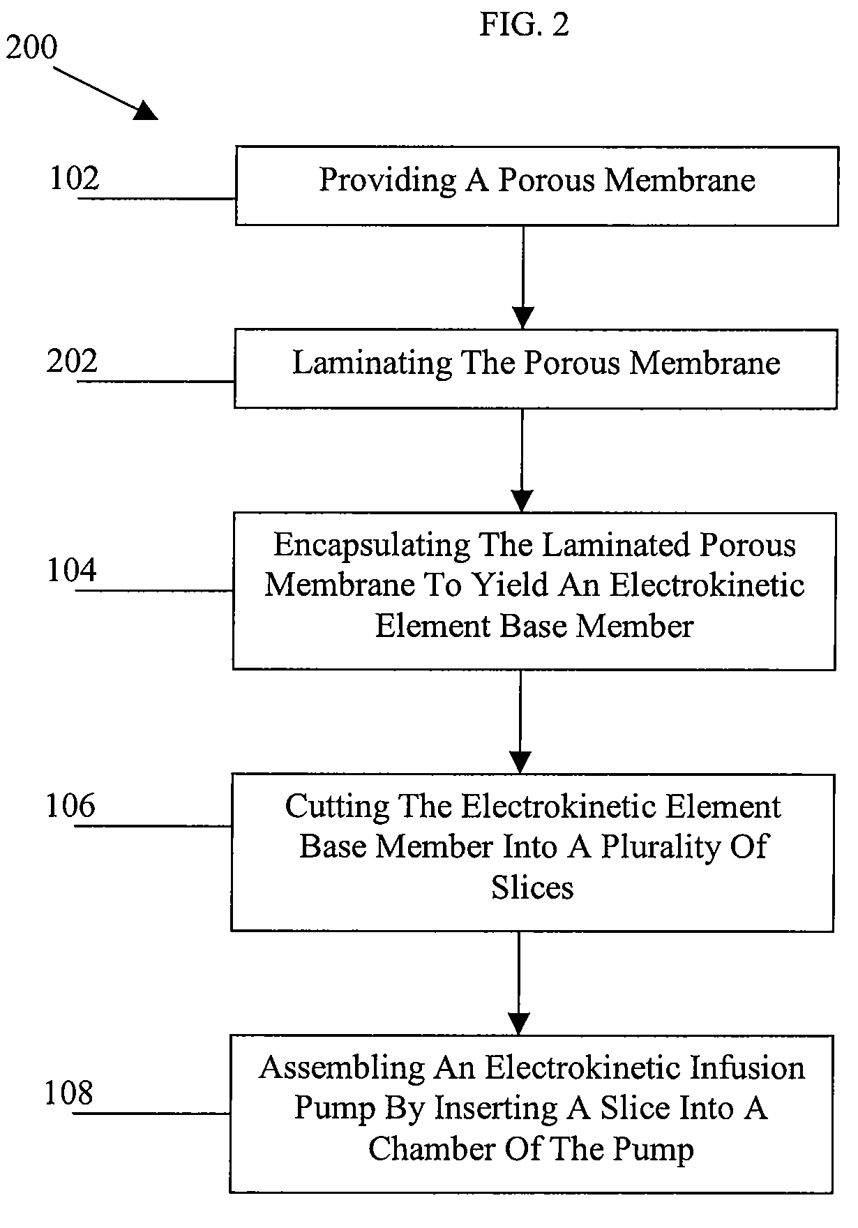
A method for preparing an electrokinetic element is provided and generally includes providing a porous membrane adapted for use in an electrokinetic pump and encapsulating the porous membrane within a polymer substrate to yield an electrokinetic element base member having the porous membrane encapsulated by the polymer. In one embodiment, the method can include laminating the porous membrane between opposed sheets of a polymer before the step of encapsulating. The method can also include cutting the electrokinetic element base member into a plurality of slices and assembling an electrokinetic infusion pump by inserting a slice into a chamber of the pump.

Description

FIELD OF THE INVENTION[0001]The present invention relates to methods for preparing an electrokinetic element for use in an infusion pump.BACKGROUND OF THE INVENTION[0002]Electrokinetic pumps provide for liquid displacement by applying an electric potential across a porous dielectric media that is filled with an ion-containing electrokinetic solution. Properties of the porous dielectric media and ion-containing solution (e.g., permittivity of the ion-containing solution and zeta potential of the solid-liquid interface between the porous dielectric media and the ion-containing solution) are predetermined such that an electrical double-layer is formed at the solid-liquid interface. Thereafter, ions of the electrokinetic solution within the electrical double-layer migrate in response to the electric potential, transporting the bulk electrokinetic solution with them via viscous interaction. The resulting electrokinetic flow (also known as electroosmotic flow) of the bulk electrokinetic s...

Claims


Application Information

Patent Timeline
Patent Type & Authority Applications(United States)
IPC IPC(8): B29C65/54B05D5/12
CPCB29C45/14778Y10T29/49236B29C47/065B29C47/067B29C70/685B29K2023/06B29K2023/083B29K2023/12B29K2025/00B29K2027/16B29K2031/04B29K2067/00B29K2075/00B29K2077/00B29K2079/085B29K2081/06B29L2031/755F04B17/00F04B19/006Y10T156/1092Y10T156/1052Y10T156/1039Y10T156/10B29C47/0021B29C48/08B29C48/21B29C48/22Y10T137/206
Inventor ZHAO, MINGQIHUANG, MARKTHOMAS, STANKRULEVITCH, PETER
Owner LIFESCAN IP HLDG LLC
Learn More