
Cooperative Routing in Wireless Networks using Mutual-Information Accumulation

a wireless network and mutual information technology, applied in data switching networks, site diversity, frequency-division multiplexes, etc., can solve the problems of non-optimal codes and other problems, and achieve the effect of reducing delay and energy usag

Inactive Publication Date: 2008-06-19
MITSUBISHI ELECTRIC RES LAB INC
View PDF24 Cites 60 Cited by
  • Summary
  • Abstract
  • Description
  • Claims
  • Application Information

AI Technical Summary

Benefits of technology

[0013]Cooperation between the nodes of wireless multi-hop networks can increase communication reliability, reduce energy consumption, and decrease latency. The improvements are even greater when nodes perform mutual-information accumulation using rateless codes, such as fountain codes. Rateless codes encode data into a potentially limitless sequence of encoded symbols, such that the data can always be reliably recovered from the encoded symbols, so long as a sufficient number of encoded symbols have been received. The embodiments described herein can be used not just with rateless codes, but with any code that enables exact or approximate accumulation of mutual information.
[0018]One embodiment uses linear programming (LP) to determine a decoding order, and allocate resources to select an optimal route. The decoding order can be improved systematically by changing the order of nodes based on the solution of the LP. The changing can include exchanging nodes in the decoding order, adding nodes to the decoding order, or removing nodes from the decoding order. Solving a sequence of LPs leads to an optimal solution in an efficient manner.
[0021]On the average, the cooperative transmission with mutual information accumulation according to the invention decreases delay and energy usage by about 70% when compared with conventional non-cooperative shortest path multihop routing.

Problems solved by technology

However, non-optimal codes can also be used.

Method used


Image

  • Cooperative Routing in Wireless Networks using Mutual-Information Accumulation
  • Cooperative Routing in Wireless Networks using Mutual-Information Accumulation
  • Cooperative Routing in Wireless Networks using Mutual-Information Accumulation

Examples


Embodiment Construction

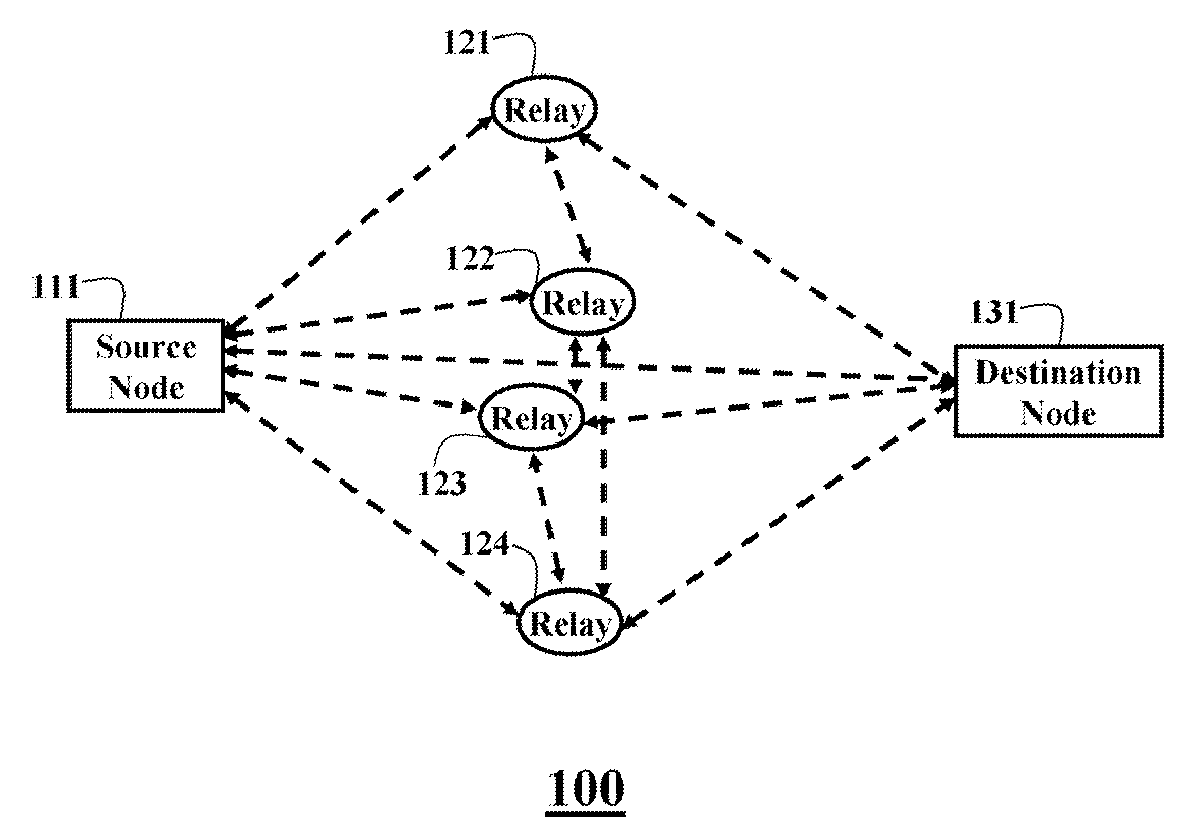
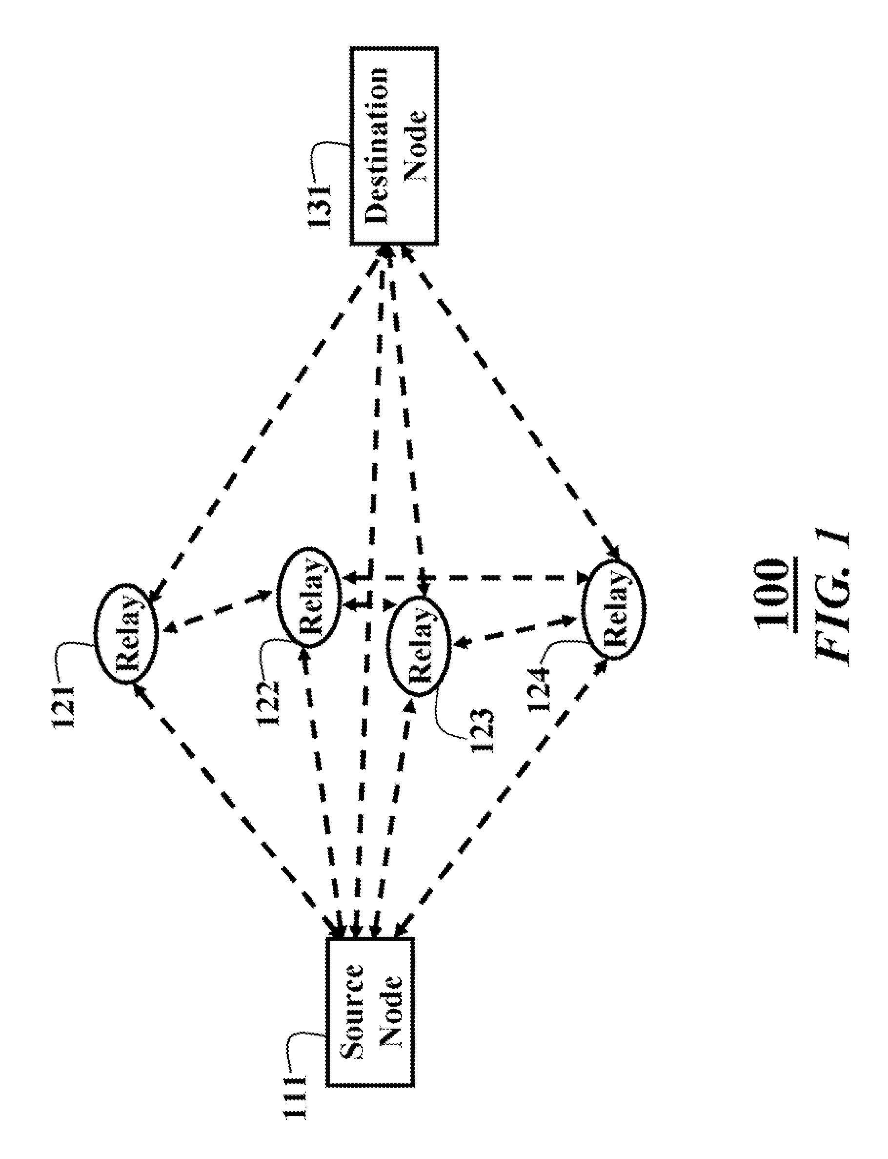
[0025]FIGS. 1 and 2 show cooperative relay networks 100 and 200 according to embodiments of our invention. The cooperative relay network 100 includes a source node 111, a set of N relay nodes 121-124, and a destination node 131, i.e., source, relays, and destination, respectively.

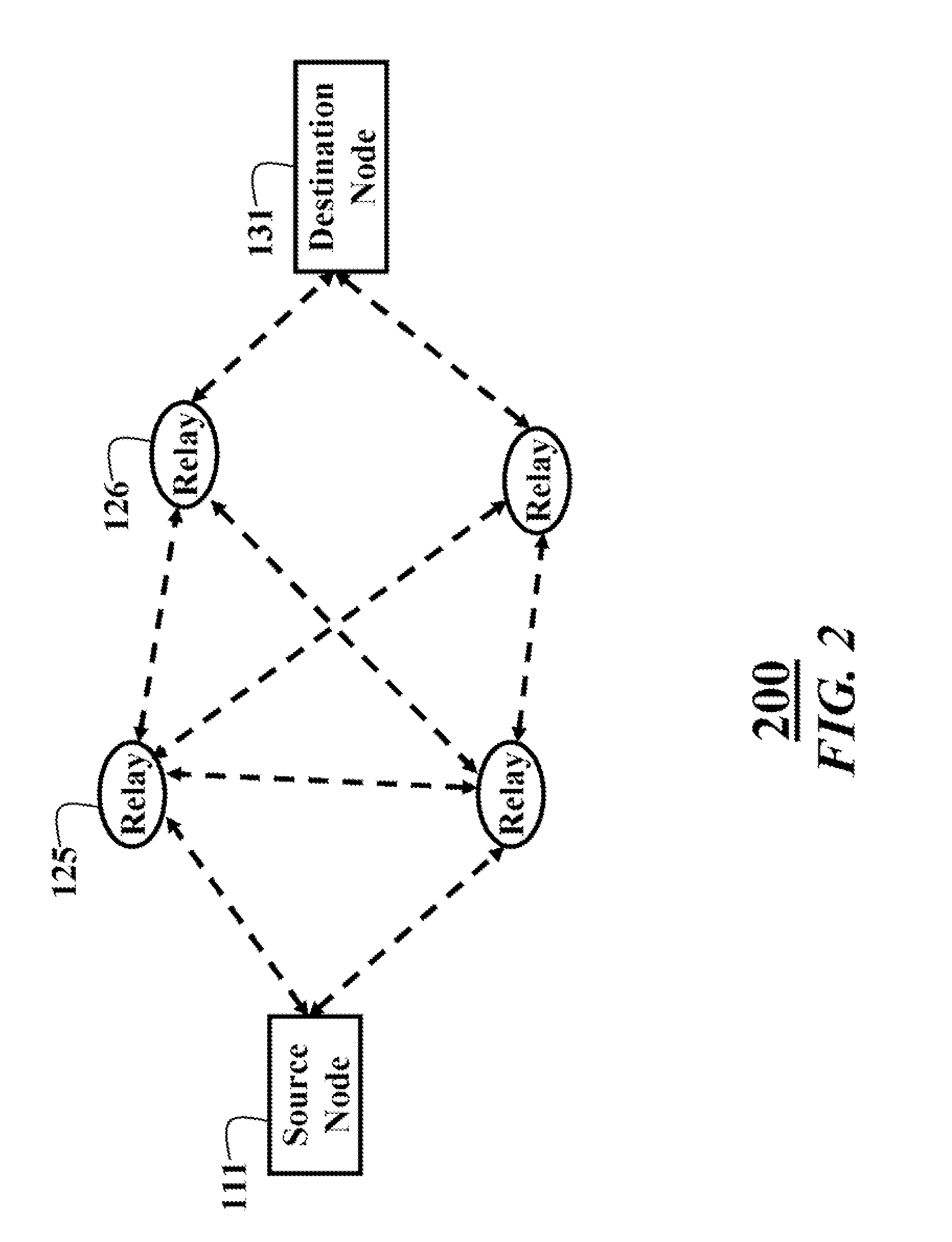
[0026]It should also be understood, that the embodiments of the invention can also by used with multiple relay ‘hops’ as shown in FIG. 2. In this case, relay 125 also acts as a ‘source’ for an ‘intermediate’ relay 126. This scheme can be extended to additional hops. It should be understood, that a practical network, such as a network of sensors in a large manufacturing plant, refinery or office building can include tens or perhaps hundreds of nodes, which makes the optimal route determination non-trivial. Particularly, brute force numerical approaches or iterative searches, as known in the art, become impractical.

[0027]It is desired to optimize resources, e.g., delay, energy or the product of time and bandw...


PUM


Abstract

A route is selected in a wireless cooperative relay network of nodes. A decoding order is initialized. A set of resources is minimized subject to constraints. The resources are allocated to the nodes in the decoding order. The decoding order is changed iteratively to further minimize the allocated resources, until a minimum is reached. A code word is transmitted when the allocated resources are at the minimum, which can either be determined globally or locally at each node. The method can operate in a centralized or distributed manner.

Description

RELATED APPLICATIONS[0001]This application is a Continuation-in-Part of U.S. patent application Ser. No. 11 / 566,846, “Route Selection in Cooperative Relay Networks,” filed by Molisch et al. on Dec. 5, 2007, which is a Continuation-in-Part of U.S. patent application Ser. No. 11 / 377,711, “Cooperative Relay Networks using Rateless Codes” filed by Molisch et al. on Mar. 16, 2006.FIELD OF THE INVENTION[0002]The invention relates generally to wireless communications networks, and more particularly to routing data in cooperative relay networks.BACKGROUND OF THE INVENTION[0003]In conventional relay networks, data are transmitted from a source node to a destination node via a single path with, perhaps, multiple serial hops through relay nodes.[0004]In a cooperative relay network, wireless nodes cooperate with each other in transmitting data in parallel. By exploiting the broadcast nature of wireless channels to reach multiple relay nodes concurrently, and by enabling the relay nodes to coope...

Claims


Application Information

Patent Timeline
IPC IPC(8): H04B7/14H04L12/56
CPCH04B7/026H04B7/15592H04B7/2606H04W52/46H04L1/0618H04L2001/0092H04L1/06
Inventor DRAPER, STARK C.LIU, LINGJIAMOLISCH, ANDREAS F.YEDIDIA, JONATHAN S.
Owner MITSUBISHI ELECTRIC RES LAB INC
Learn More