Antenna apparatus provided with antenna element excited through multiple feeding points
a technology of antenna elements and antenna elements, applied in the field of antenna apparatus, can solve the problems of complex structure, inability of mobile radio apparatus to simultaneously implement a plurality of states, and inability to simultaneously implement a plurality of states, and achieve the effect of reducing the number of antenna elements, simple configuration, and low correlation
- Summary
- Abstract
- Description
- Claims
- Application Information
AI Technical Summary
Benefits of technology
Problems solved by technology
Method used
Image
Examples
first preferred embodiment
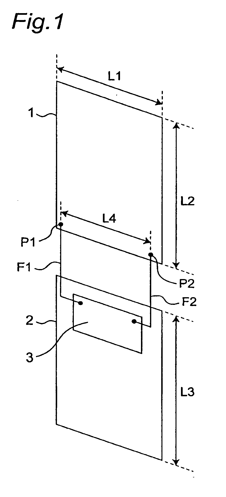
[0074]FIG. 1 is a perspective view showing a schematic configuration of an antenna apparatus according to a first preferred embodiment of the present invention. The antenna apparatus of the present preferred embodiment is characterized in that it includes a rectangular antenna element 1 having two different feeding points P1 and P2, and makes the single antenna element 1 operate as two antenna portions, by exciting the antenna element 1 as a first antenna portion through the feeding point P1, and at the same time, exciting the antenna element 1 as a second antenna portion through the feeding point P2.
[0075]In FIG. 1, the antenna apparatus includes the antenna element 1 made of a rectangular conductive plate with a horizontal length L1×a vertical length L2, and a ground conductor 2 made of a rectangular conductive plate with a horizontal length L1×a vertical length L3. The antenna element 1 and the ground conductor 2 are juxtaposed to be spaced from each other by a certain distance, ...
second preferred embodiment
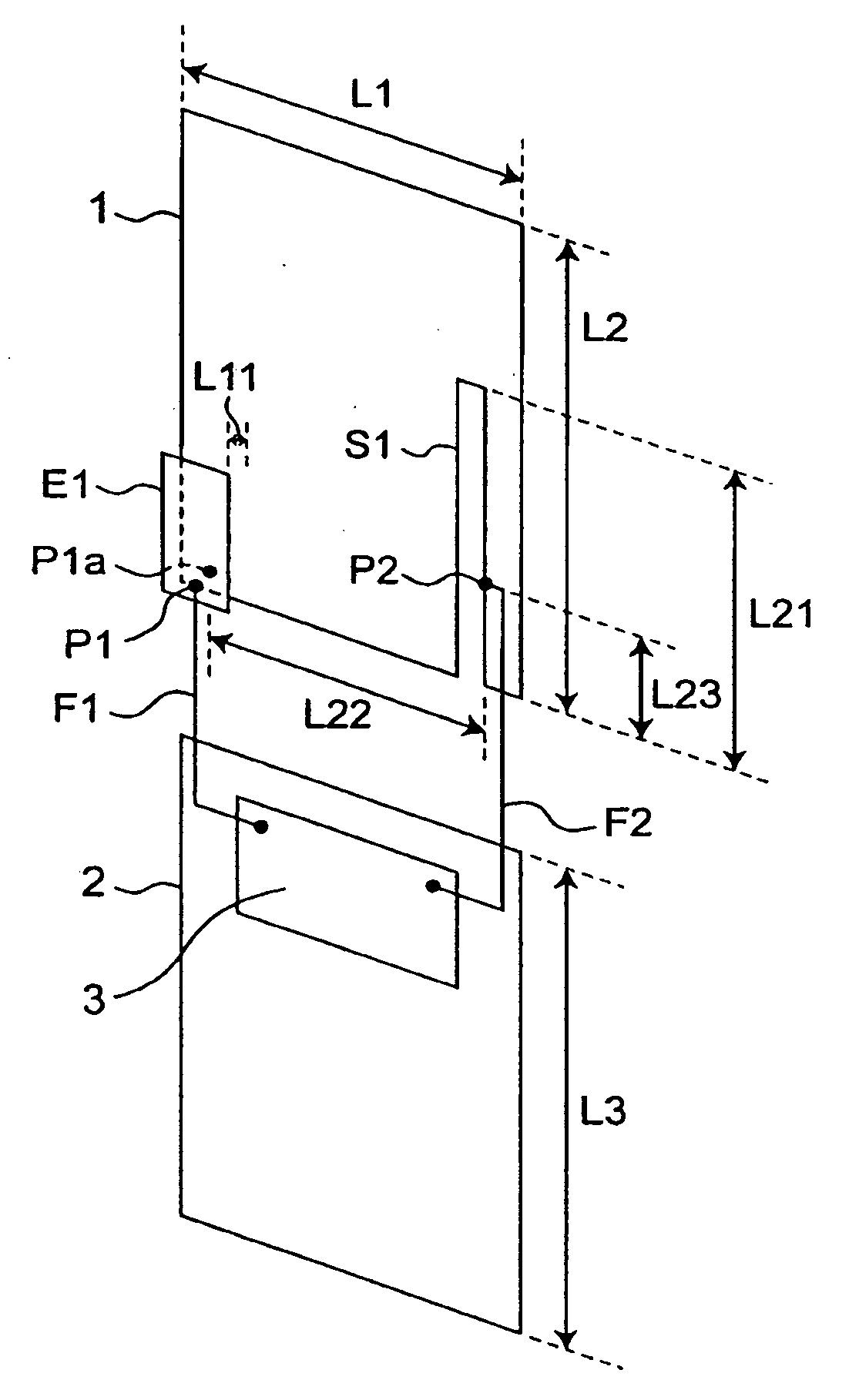
[0084]FIG. 6 is a perspective view showing a schematic configuration of an antenna apparatus according to a second preferred embodiment of the present invention. Although in the antenna apparatus of the first preferred embodiment the radio signal is directly fed to the antenna element 1 at both of the feeding points P1 and P2, the antenna apparatus of the second preferred embodiment is characterized by that a radio signal is capacitively fed (fed through a capacitor) to a antenna element 1 at one of the feeding points P1 and P2 in FIG. 1, i.e., at a feeding point P1.
[0085]In FIG. 6, the antenna apparatus is provided with an electrode E1, which is made of a conductive plate and provided in parallel to an antenna element 1 at a position where the feeding point P1 is provided in FIG. 1. The electrode E1 is spaced from the antenna element 1 by a certain distance L11 through air or a certain dielectric material. Thus, in the antenna apparatus of the present preferred embodiment, a capaci...
third preferred embodiment
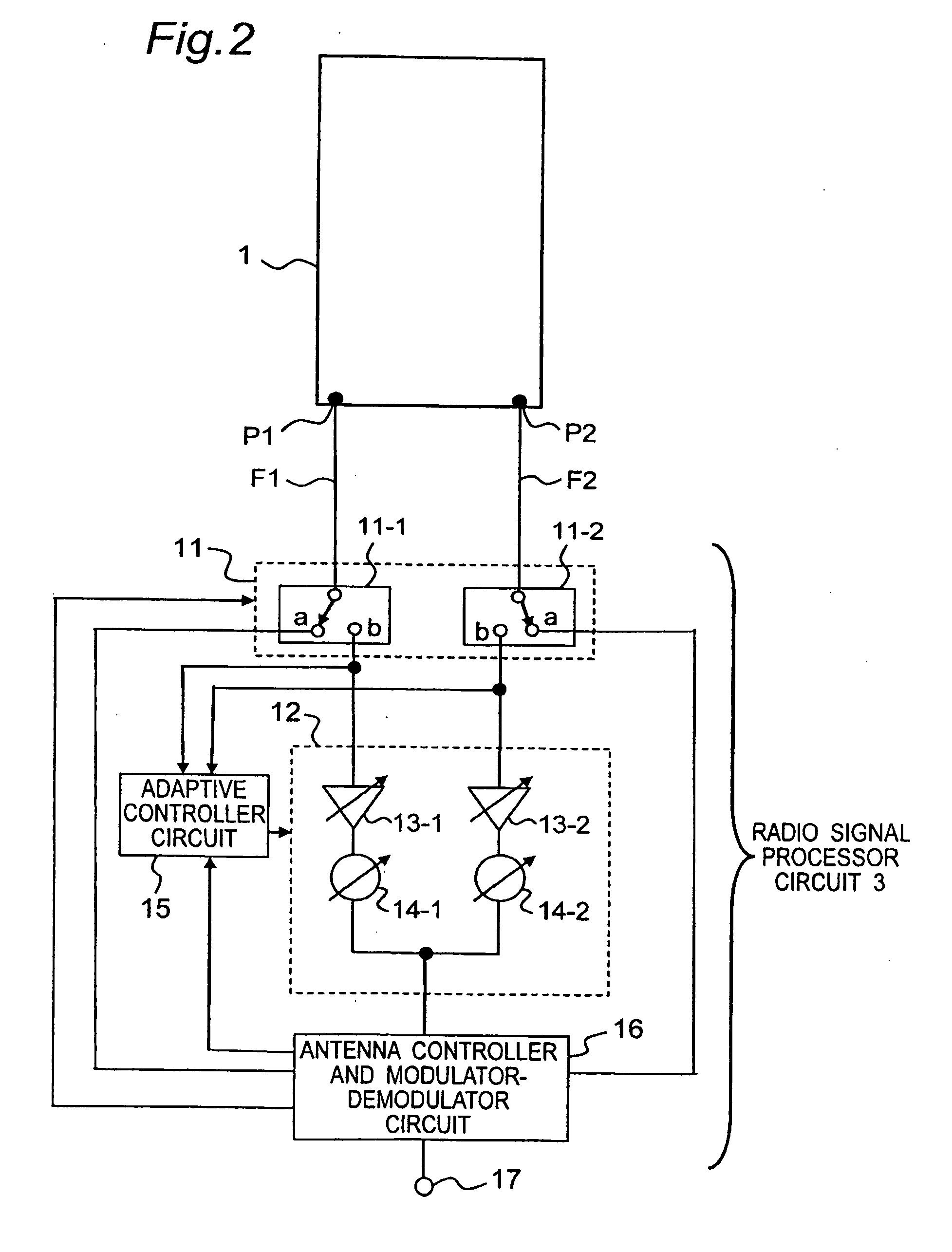
[0092]FIG. 10 is a perspective view showing a schematic configuration of an antenna apparatus according to a third preferred embodiment of the present invention, and FIG. 11 is a block diagram showing a detailed configuration of a circuit of the antenna apparatus in FIG. 10. Although in the antenna apparatus of the second preferred embodiment the antenna element 1 operates as an electric current antenna (i.e., an antenna in which the antenna element 1 acts as an electric current source) in each of both cases in which the radio signal is capacitively fed to the antenna element 1 through the feeding point P1 and in which the radio signal is fed directly to the antenna element 1 through the feeding point P2, the antenna apparatus of the third preferred embodiment is characterized in that the antenna apparatus further has a slit S1, and when a radio signal is fed to the slit S1 through a feeding point P2, the slit S1 is made to operate as a magnetic current antenna (i.e., an antenna in ...
PUM
 Abstract
Description
Claims
Application Information
 - R&D
- Intellectual Property
- Life Sciences
- Materials
- Tech Scout
- Unparalleled Data Quality
- Higher Quality Content
- 60% Fewer Hallucinations
Browse by: Latest US Patents, China's latest patents, Technical Efficacy Thesaurus, Application Domain, Technology Topic, Popular Technical Reports.
© 2025 PatSnap. All rights reserved.Legal|Privacy policy|Modern Slavery Act Transparency Statement|Sitemap|About US| Contact US: help@patsnap.com


