
Highly trackable balloon catheter system and method for collapsing an expanded medical device

Active Publication Date: 2008-06-12
ABBOTT CARDIOVASCULAR
View PDF38 Cites 35 Cited by
  • Summary
  • Abstract
  • Description
  • Claims
  • Application Information

AI Technical Summary

Benefits of technology

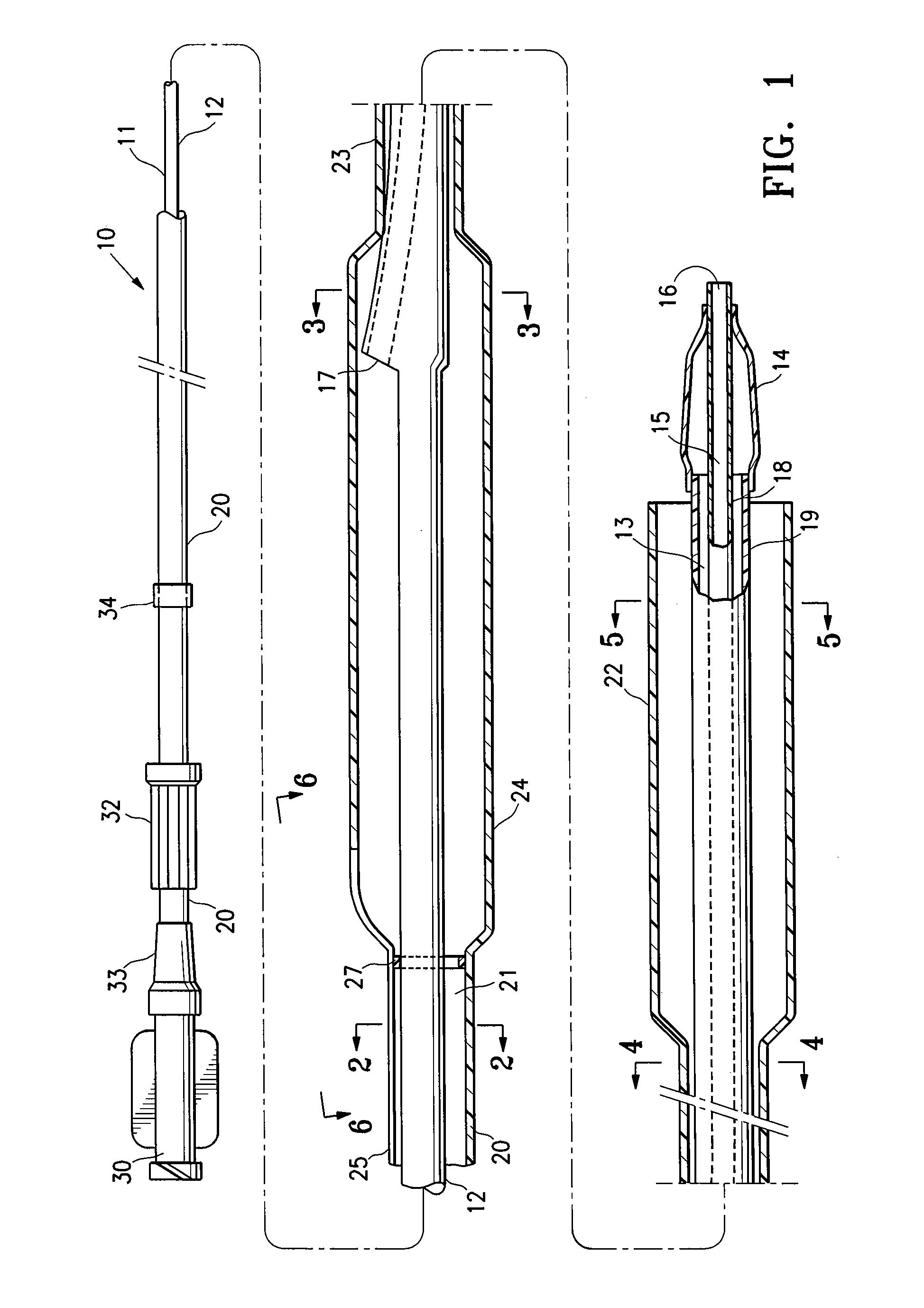
[0008]In a presently preferred embodiment, the recovery sheath has a transverse cross sectional profile which decreases from a large profile distal recovery section to smaller profile distal shaft section, and which increases from the distal shaft section to a larger profile midshaft section, and which decreases from the midshaft section to a smaller profile proximal shaft section. Typically, the balloon catheter is a rapid exchange-type catheter having a proximal shaft section and a distal shaft section with the device lumen extending in the distal shaft section to a proximal port spaced distally from the proximal end of the elongated catheter shaft, and the variable profile sheath is configured to closely conform to the underlying balloon catheter shaft. As a result, the extent to which the sheath increases the stiffness and profile of the balloon catheter is minimized, thus providing a corresponding improvement in the ability to track the balloon catheter with the sheath mounted thereon on a guidewire or other device.
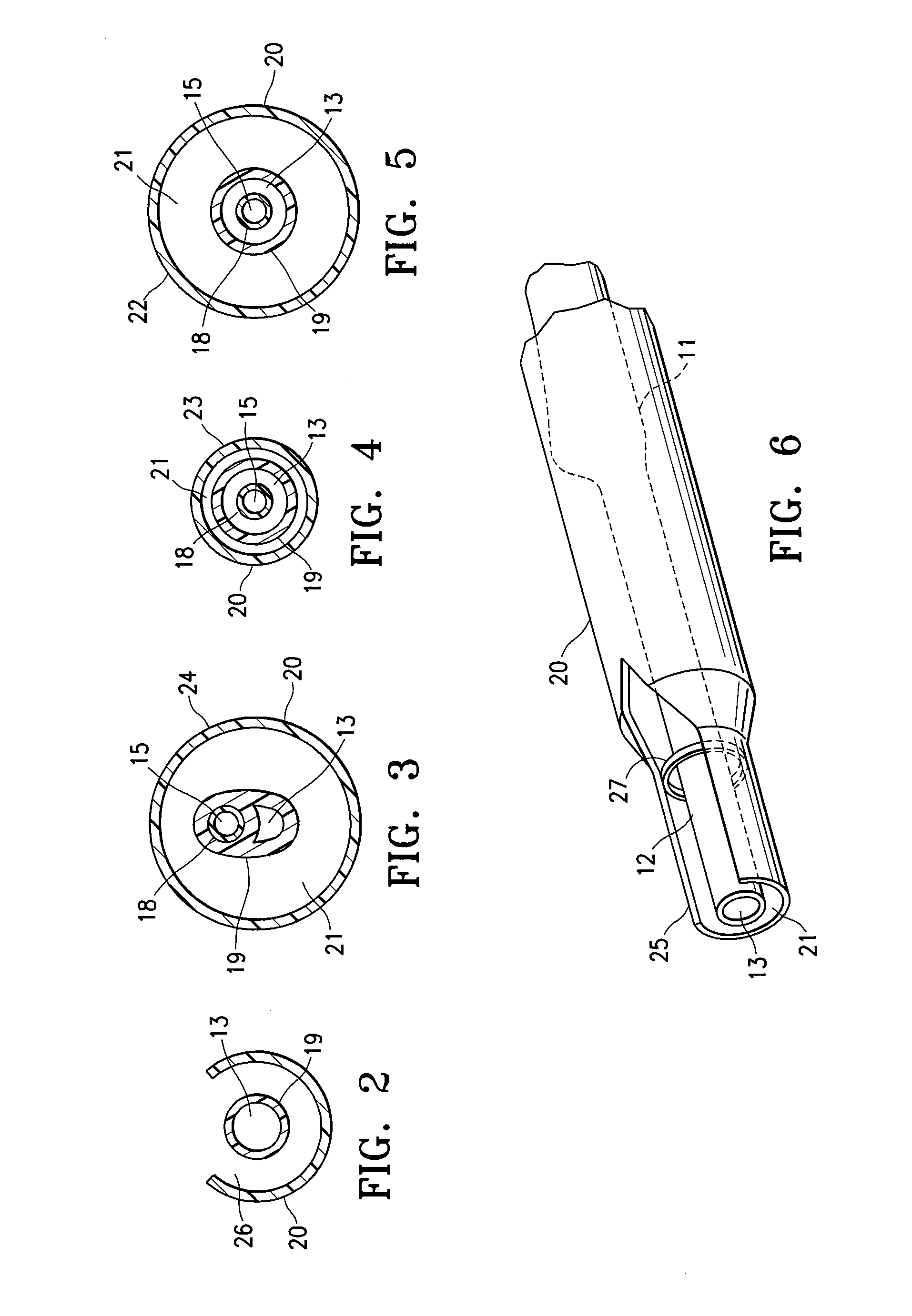
[0009]The recovery sheath has at least a section with a tubular body such that the increasing and decreasing profile of the sheath forms internal shoulders therein (i.e., at the location of a change in the diameter of the sheath lumen). In a presently preferred embodiment, the internal shoulders of the sheath are configured to act as a stop, thereby limiting the longitudinal advancement or retraction of the sheath therealong by contacting underlying portions of the balloon catheter.
[0010]In one embodiment, the sheath has a section having an open-walled configuration, preferably with a C-shaped inner surface, which defines a channel and which is configured to extend only partially around the circumference of the elongated shaft of the balloon catheter. Such an open-walled section extending along a proximal portion of the sheath facilitates providing the sheath on a rapid-exchange type balloon catheter. Additionally, the open-walled section further improves trackability of the system by minimizing the profile and stiffness increases resulting from the sheath on the balloon catheter.
[0011]In one embodiment, the distal recovery section of the recovery sheath has at least a portion with a corrugated wall which unfolds from a radially collapsed configuration to a radially enlarged configuration. The corrugated distal recovery portion is preferably configured to unfold and thereby radially expand upon application of a radially expansive force against an inner surface of the distal recovery portion in the collapsed configuration. In a presently preferred embodiment, the corrugated wall self-collapses to a radially re-collapsed configuration from the radially enlarged configuration upon the removal of the radially expansive force. As a result, the corrugated tip of the recovery sheath provides a very low profile distal leading end which facilitates advancing the catheter system within the patient's anatomy, while also providing the sheath with an inner lumen which is sized to effectively collapse the expanded device, e.g., embolic protection device.
[0012]The recovery sheath has an inner diameter along at least a portion of the distal recovery section of the sheath which is sufficiently large to facilitate sliding the sheath along an expanded operative distal end of the expanded device in order to collapse the operative distal end, e.g., the expanded filter of an embolic protection device. The larger diameter distal recovery section of the sheath reduces the force required to slidably advance the sheath during collapse of an embolic protection device therein (i.e., relative to the smaller diameter shaft section of the sheath located proximal to the larger diameter distal recovery section of the sheath), such that the relatively low detach force of common embolic protection devices is not exceeded. For example, in one embodiment the expandable device (e.g., embolic protection device) has an elongated body which has an expanding frame secured to a distal section thereof with a detach force of less than 1 pound, and the recovery section of the sheath has an inner diameter configured to be slidably advanceable over the frame, to collapse the frame, with a force which does not exceed the detach force of the frame.
[0014]A balloon catheter system of the invention provides excellent flexibility and low profile due to the profile changes along the length thereof. The system is therefore highly trackable, yet avoids the need to withdraw the balloon catheter from the treatment site before an expanded device, e.g., embolic protection filter, can be recovered within a recovery catheter. As a result, the system provides for ease of use, and minimizes the procedure time. These and other advantages of the invention will become more apparent from the following detailed description and accompanying exemplary drawings.

Problems solved by technology

Such intravascular procedures may release emboli into the circulatory system, which can be extremely dangerous to the patient.
Debris that is carried by the bloodstream to distal vessels of the brain may cause these cerebral vessels to occlude, resulting in a stroke, and in some cases, death.
However, the catheter shaft must also retain sufficient flexibility and low profile to allow it to track over a guidewire through the often tortuous, narrow vasculature.
As a result, one design challenge has been making the procedure, including the delivery and retrieval of the components of the catheter system, as quick and easy as possible.

Method used


Image

  • Highly trackable balloon catheter system and method for collapsing an expanded medical device
  • Highly trackable balloon catheter system and method for collapsing an expanded medical device
  • Highly trackable balloon catheter system and method for collapsing an expanded medical device

Examples


Embodiment Construction

[0026]FIG. 1 illustrates an elevational, partially in section, view of a balloon catheter system 10 embodying features of the invention, generally comprising a balloon catheter 11 having elongated catheter shaft 12 with an inflatable balloon 14 secured to a distal shaft section, and a recovery sheath 20 on the elongated catheter shaft 12 configured to slidably receive at least a portion of an expandable section of an expandable device such as an embolic protection device 40 (see FIG. 8). The inflatable balloon 14 has an interior in fluid communication with an inflation lumen 13 extending within the shaft 12, so that the balloon inflates from a noninflated configuration to an inflated configuration upon the introduction of inflation fluid to the balloon interior, and deflates to a deflated configuration upon the withdrawal of the inflation fluid. FIG. 1 illustrates the balloon 14 in the low profile noninflated configuration for introduction and advancement within the patient's body l...


PUM


Abstract

A balloon catheter having a pre-mounted recovery sheath for recovering an expanded device, such as an embolic protection device, in a patient's body lumen, and a method of using a balloon catheter system of the invention to recover the expanded device

Description

BACKGROUND OF THE INVENTION[0001]This application is a continuation-in-part of U.S. application Ser. No. 11 / 567,682, filed Dec. 6, 2006, the contents of which are incorporated by reference.[0002]The present invention relates generally to interventional catheters, and more particularly to a balloon catheter configured for use in an intravascular medical procedure in a stenosed blood vessel.[0003]The treatment of an occluded region of a patient's vasculature commonly includes a percutaneous transluminal interventional procedure such as inflating a catheter balloon and / or implanting a stent inside the blood vessel at the site of the stenosis. For example, in balloon angioplasty, the catheter balloon is positioned across the lesion and inflated with fluid one or more times to a predetermined size at relatively high pressures (e.g. greater than 8 atmospheres) so that the stenosis is compressed against the arterial wall and the wall expanded to clear the passageway. Physicians frequently ...

Claims


Application Information

Patent Timeline
IPC IPC(8): A61M25/10A61F2/958
CPCA61F2230/0006A61F2/013A61F2/011
Inventor BEI, NIANJIONG JOANLUBAS, JOANNAMONTANO-MORSE, ANA
Owner ABBOTT CARDIOVASCULAR
Learn More