Heat dissipation module

Inactive Publication Date: 2008-06-05
HON HAI PRECISION IND CO LTD
View PDF20 Cites 6 Cited by
  • Summary
  • Abstract
  • Description
  • Claims
  • Application Information

AI Technical Summary

Benefits of technology

[0010]One advantage of the present invention is that a total contact surface area between the heat generating component and the block is dramatically increased due to the existence of the groove of the block. The heat generating component is fittingly received in the groove and brought into contact with the block three-dimensionally. Thus, the heat dissipation efficiency of the heat dissipation module can be greatly enhanced.
is that a total contact surface area between the heat generating component and the block is dramatically increased due to the existence of the groove of the block. The heat generating component is fittingly received in the groove and brought into contact with the block three-dimensionally. Thus, the heat dissipation efficiency of the heat dissipation module can be greatly enhanced.

Problems solved by technology

Because of the miniaturization of the processor, the contact surface area between the processor and the thermal contact block is limited, affecting the heat transfer rate from the processor to the thermal contact block, and accordingly decreasing the efficiency of the heat dissipation module.

Method used


Image

  • Heat dissipation module
  • Heat dissipation module
  • Heat dissipation module

Examples


Embodiment Construction

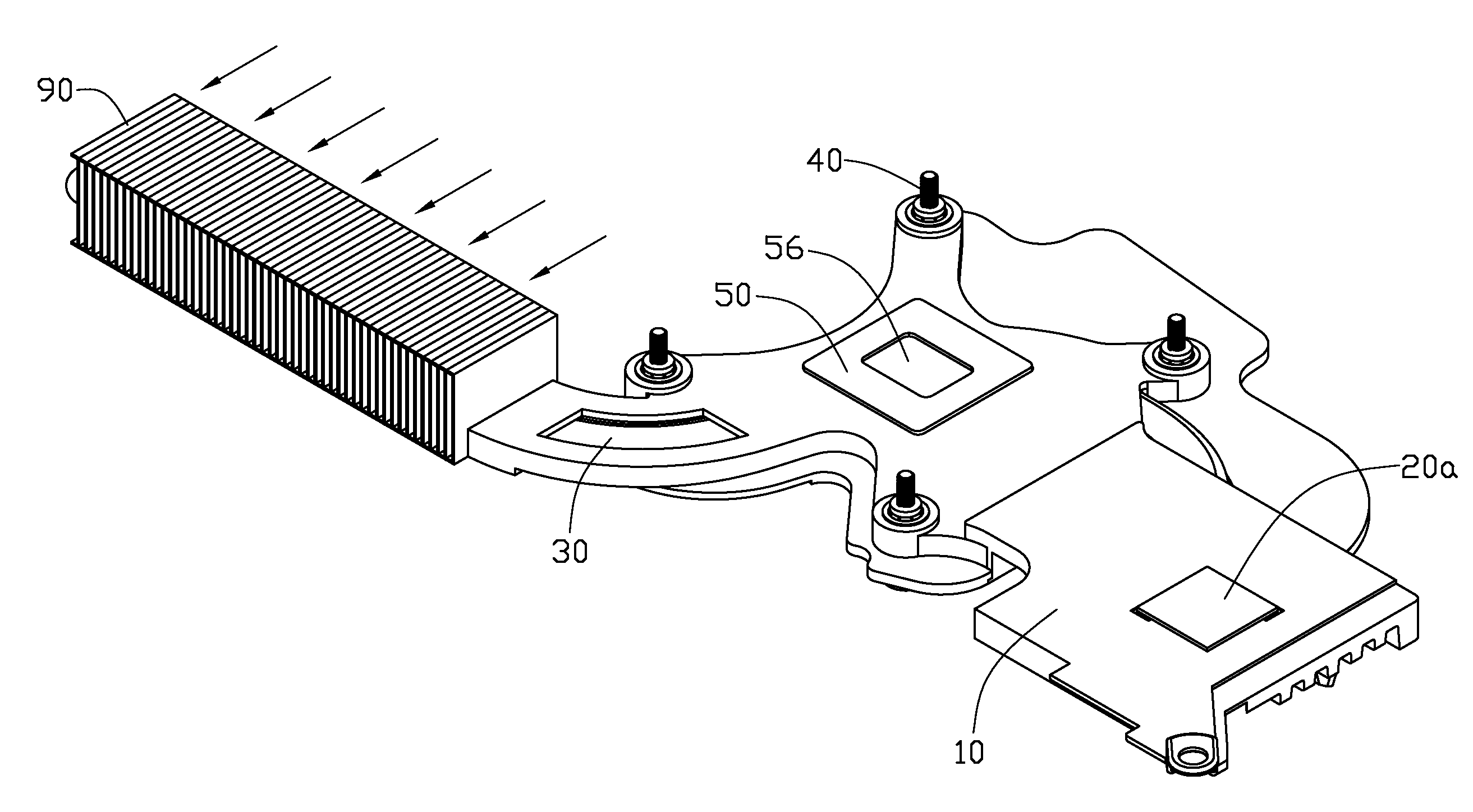
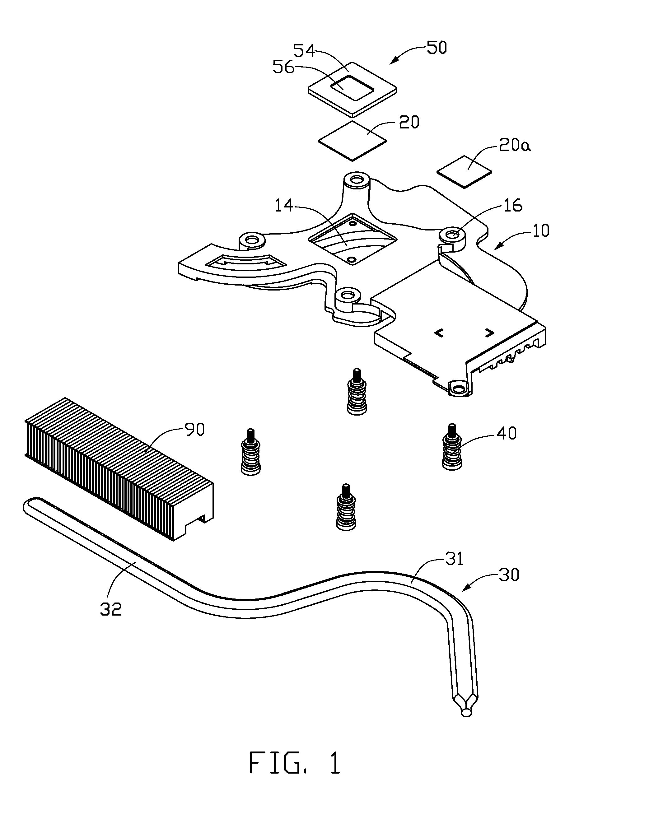
[0017]Referring to FIG. 1, FIG. 2 and FIG. 3, a heat dissipation module in accordance with a preferred embodiment of the present invention comprises a mounting seat 10, a heat pipe 30, a fin unit 90 and a thermal contact block 50.

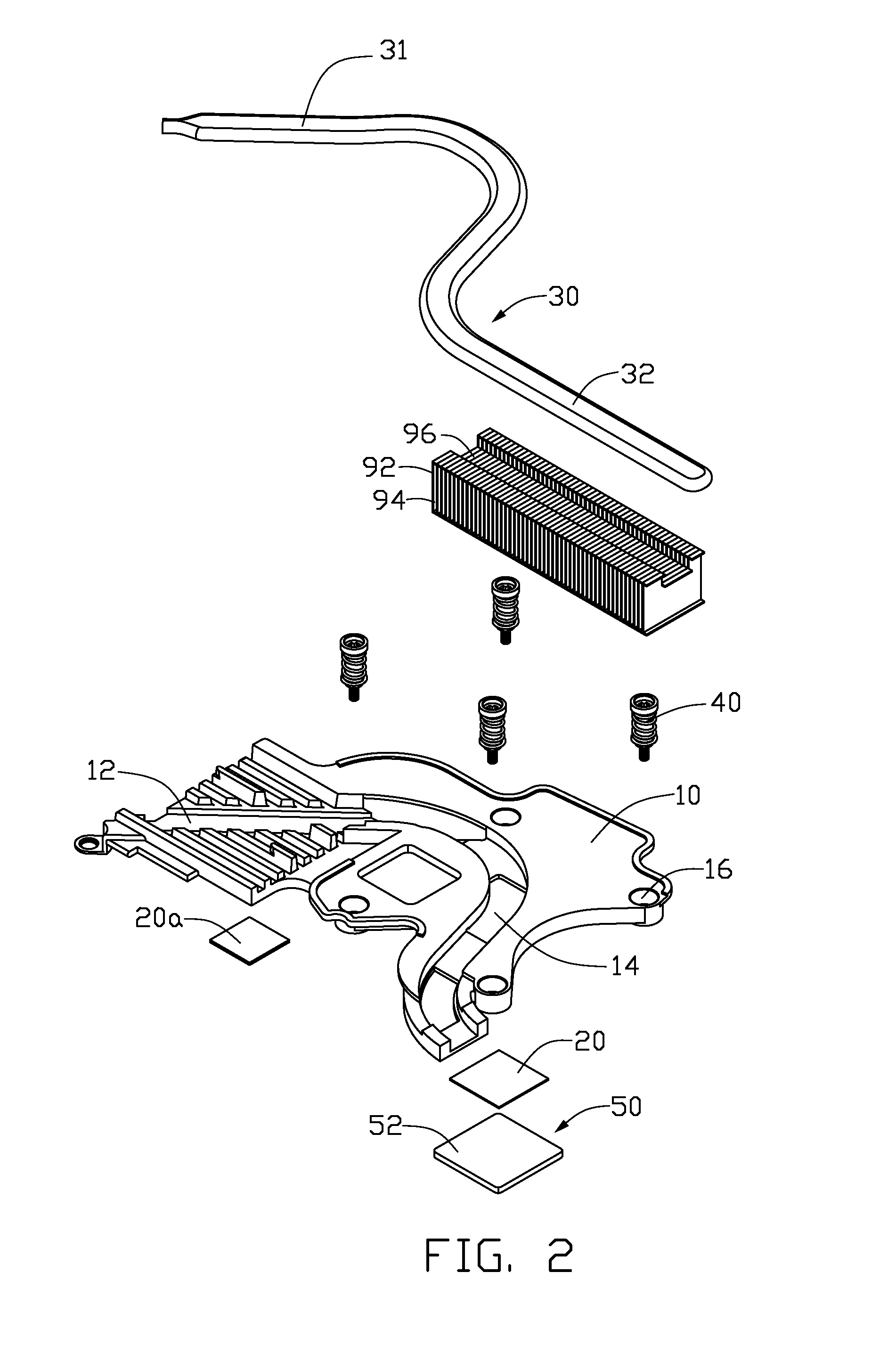
[0018]A square-shaped receiving groove 14 is defined in a substantially central area of a top side of the mounting seat 10 for receiving the block 50 therein. A plurality of setting holes 16 are defined around the receiving groove 14 for allowing spring-loaded screws 40 to extend therethrough to secure the mounting seat 10 to a mainboard (not shown), such as a circuit board of a notebook computer. An arc-shaped groove 12 is defined in a bottom side of the mounting seat 10 for receiving the heat pipe 30 therein. The receiving groove 14 is connected to and communicates with the groove 12, in a manner such that the heat pipe 30 disposed in the groove 12 can be thermally connected to the block 50 disposed in the receiving groove 14.

[0019]The fin unit 90 compris...


PUM


Abstract

A heat dissipation module for removing heat from a heat generating component, includes a block, a heat pipe and a fin unit. The block includes a first surface and a second surface. One end of the heat pipe is thermally attached to the fin unit, and the other end of the heat pipe is thermally attached to the first surface of the block. A groove is defined in the second surface of the block for fittingly receiving the heat generating component therein.

Description

BACKGROUND OF THE INVENTION [0001]1. Field of the Invention[0002]The present invention generally relates to a heat dissipation module, and more particularly to a heat dissipation module for electronic elements.[0003]2. Description of the Related Art[0004]With the advance of large scale integrated circuit technology, and the widespread use of computers in all trades and occupations, in order to meet the required improvement in data processing load and request-response times, high speed processors have become faster and faster, which causes the processors to generate redundant heat. Redundant heat that is not quickly removed will have tremendous influence on the system security and performance.[0005]To solve this problem of heat generated by the processor, a heat dissipation module is often mounted on the processor for dissipating heat. For enhancing the heat dissipation capability of the heat dissipation module, a thermal contact block is arranged for thermally contacting with the pr...

Claims


Application Information

Patent Timeline
IPC IPC(8): H05K7/20
CPCF28D15/0266F28F1/24G06F1/20H01L23/427H01L2924/0002H01L2924/00
Inventor CHEN, YUN-SHENG
Owner HON HAI PRECISION IND CO LTD
Why Eureka
Try Eureka