
Disk drive with nonvolatile memory for storage of failure-related data

a technology of failure-related data and non-volatile memory, which is applied in the field of magnetic recording disk drives, can solve the problems of failure events to be monitored and recorded, defective data sectors, etc., and achieve the effect of facilitating the repair or re-design of future hdds and greater storage capacity

Inactive Publication Date: 2008-06-05
WESTERN DIGITAL TECH INC
View PDF32 Cites 92 Cited by
  • Summary
  • Abstract
  • Description
  • Claims
  • Application Information

AI Technical Summary

Benefits of technology

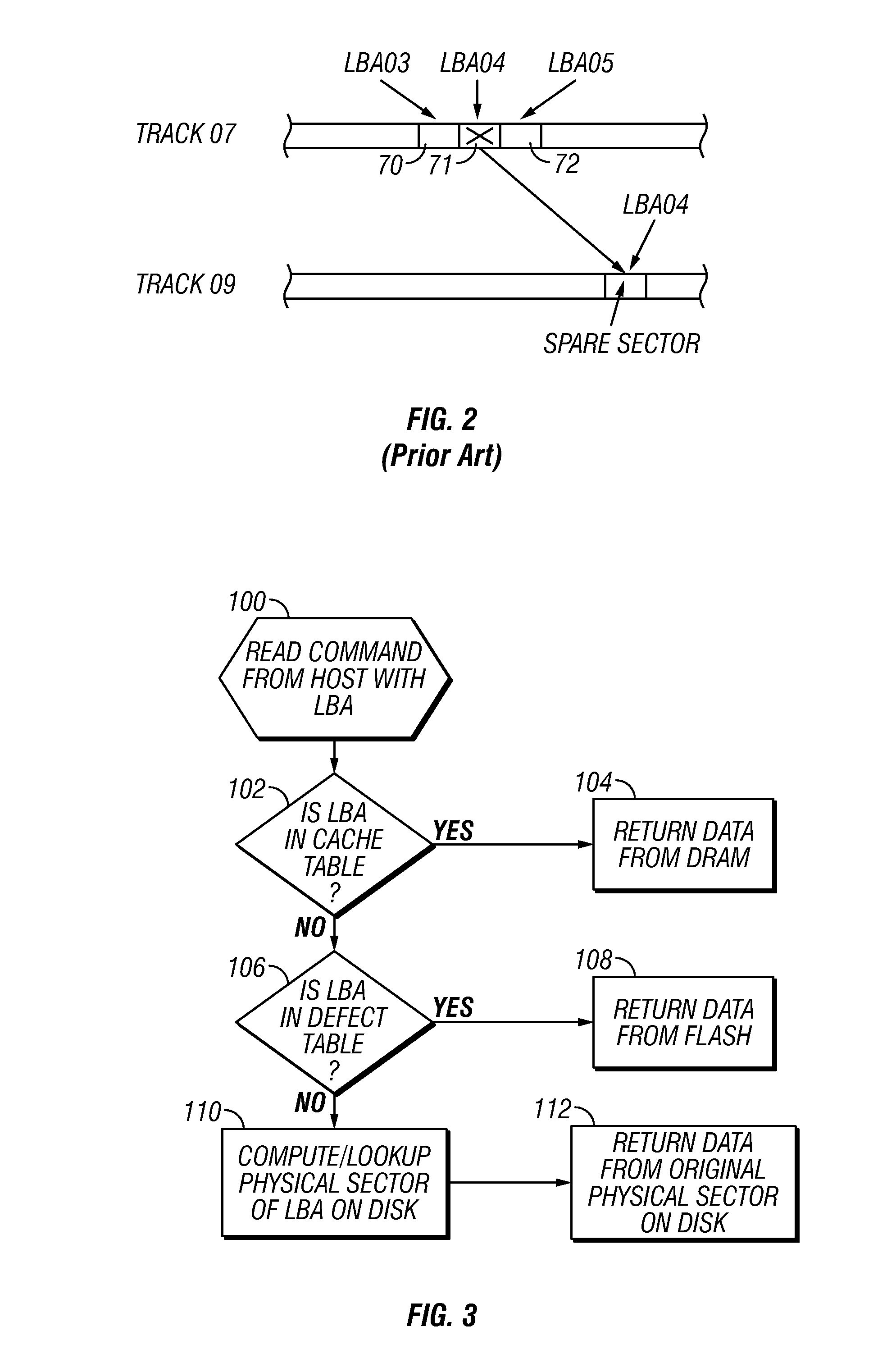
The invention is a hybrid disk drive that monitors reliability-related parameters to detect potential hard disk drive (HDD) failure events and records failure-related data in nonvolatile memory, rather than in reserved areas of the disks. This monitoring may be done by running a diagnostic routine or by sensors on the HDD. The failure events to be monitored include defective data sectors, which can be detected by running a diagnostic routine or by a defect management routine. When a new defective sector is detected after the HDD has been put into operation, that sector is taken out of service and its LBA is mapped to a memory space in the nonvolatile memory rather to a reserved spare sector on the disk. The user data that would have been stored in the defective sector is considered like failure data and is stored in the associated memory space in nonvolatile memory. This invention allows the HDD to have greater storage capacity because reserved areas of the disks are not required to store failure-related data, including reserved spare sectors for storing user data associated with defective sectors.

Problems solved by technology

The failure events to be monitored and recorded may include defective data sectors.

Method used


Image

  • Disk drive with nonvolatile memory for storage of failure-related data
  • Disk drive with nonvolatile memory for storage of failure-related data
  • Disk drive with nonvolatile memory for storage of failure-related data

Examples


Embodiment Construction

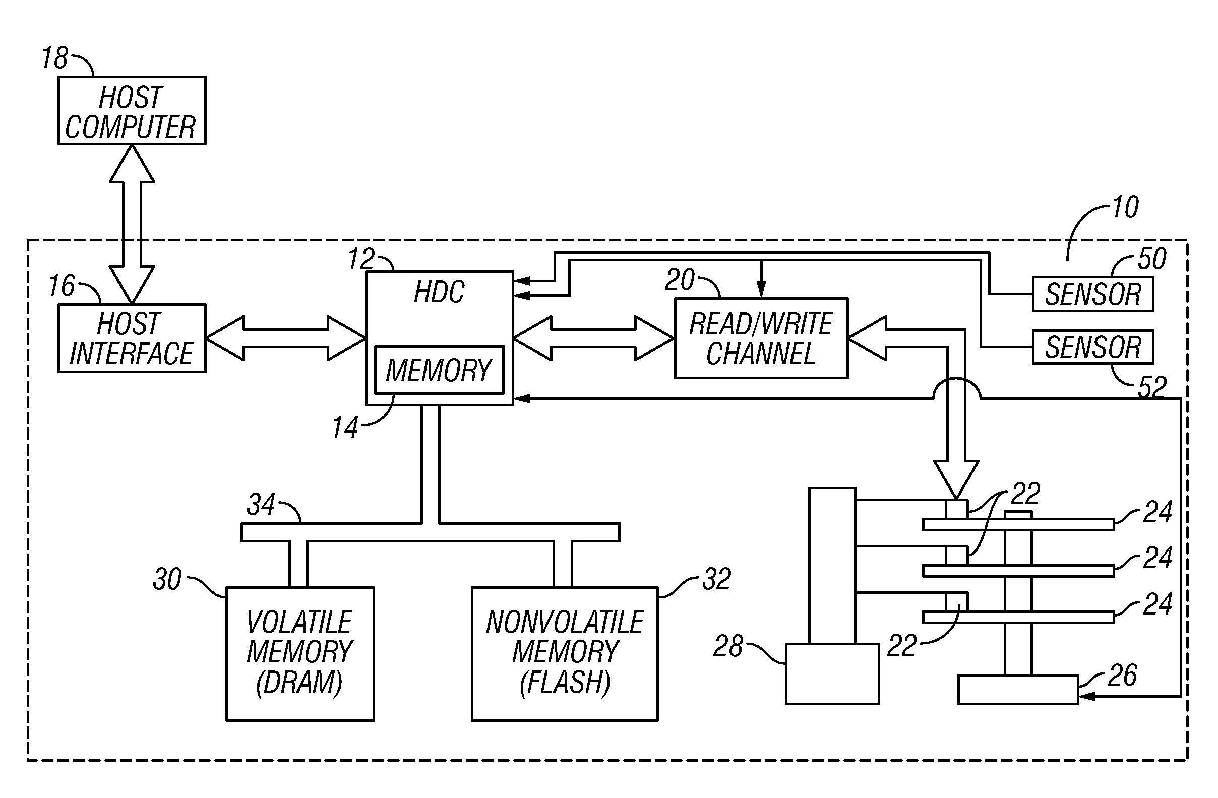
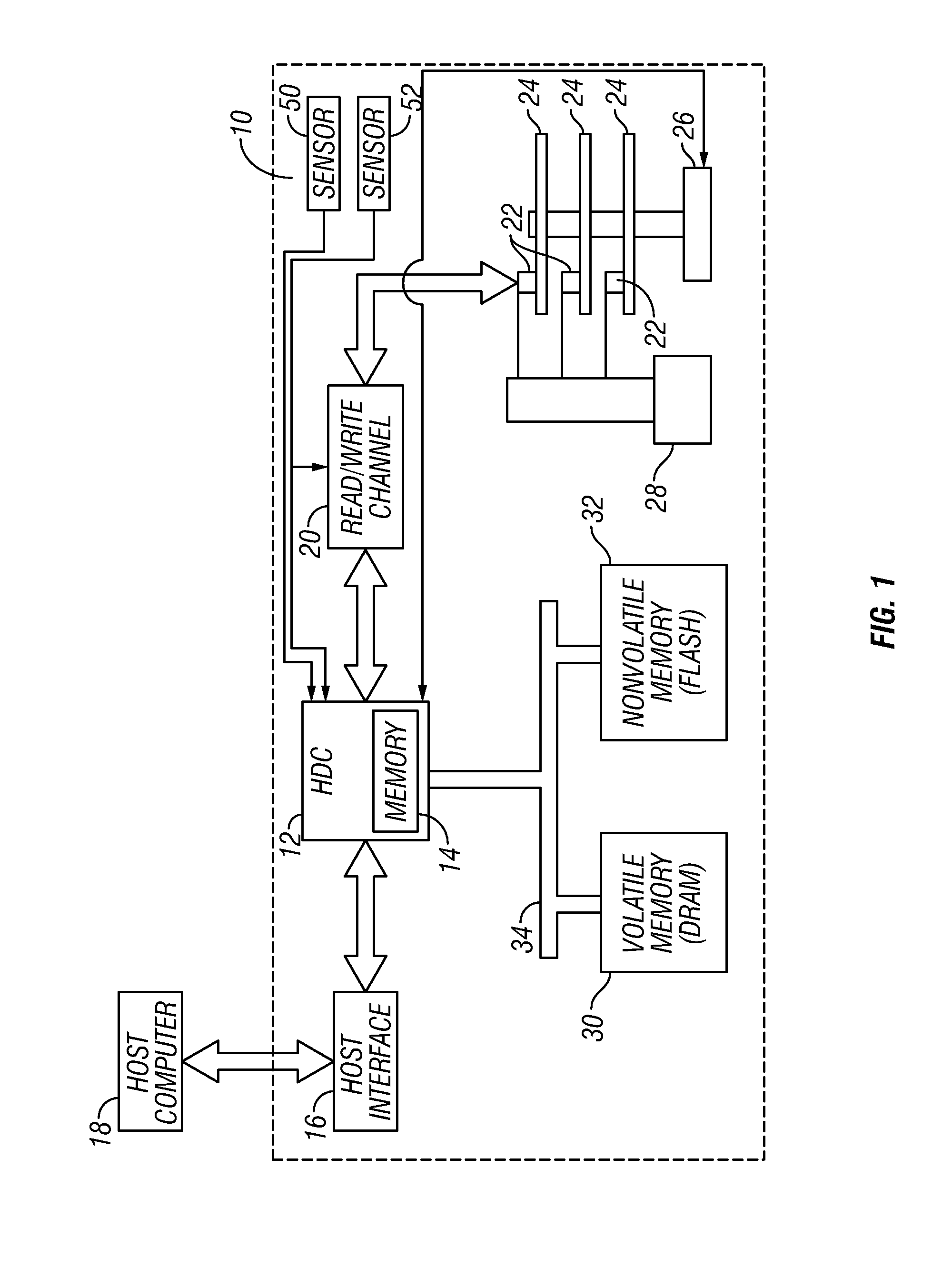
[0018]FIG. 1 is a block diagram of a magnetic recording hybrid hard disk drive (HDD) 10 according to this invention. The HDD 10 includes a hard disk controller (HDC) 12 that can include and / or be implemented by a microcontroller or microprocessor. The controller 12 runs a computer program that is stored in memory 14 and that embodies the logic and algorithms described further below. The memory 14 may be separate from controller 12 or as embedded memory on the controller chip. The computer program may also be implemented in microcode or other type of memory accessible to the controller 12.

[0019]The controller 12 is connected to a host interface 16 that communicates with the host computer 18. The host computer 18 may be a portable computer that can operate from battery power. The host interface 16 may be any conventional computer-HDD interface, such as Serial ATA (Advanced Technology Attachment) or SCSI (Small Computer System Interface).

[0020]The controller 12 is also connected to eac...


PUM

PropertyMeasurementUnit
temperatureaaaaaaaaaa
thresholdaaaaaaaaaa
volatileaaaaaaaaaa

Abstract

A disk drive that includes nonvolatile memory monitors the drive's reliability-related parameters to detect real or potential failure events, and records failure-related data in nonvolatile memory, rather than in reserved areas of the disks. The monitoring may be by running a diagnostic routine or by regular or periodic monitoring of disk drive sensors, like temperature and shock sensors. The failure events to be monitored and recorded may include defective data sectors. When a new defective sector is detected after the disk drive has been put into operation, that defective sector is taken out of service and its logical block address (LBA) is mapped to a memory space in the nonvolatile memory rather to a reserved spare sector on the disk. When a read or write command is received for an LBA range that includes the defective sector's LBA, the defective sector is skipped while the whole LBA range of the command is processed and the user data for the defective sector's LBA is read from or written to the mapped memory space in the nonvolatile memory.

Description

BACKGROUND OF THE INVENTION[0001]1. Field of the Invention[0002]This invention relates generally to disk drives, and more particularly to a magnetic recording disk drive that includes a nonvolatile memory.[0003]2. Description of the Related Art[0004]Magnetic recording hard disk drives (HDDs) typically include, in addition to the rotating disk memory, dynamic random access memory (DRAM), a volatile form of memory that can undergo a significant number of write / erase cycles and that has a high data transfer rate. The DRAM functions as “cache” to temporarily hold user data transferred between the host computer and the disks. The disk drive's data controller receives read and write commands from the host computer and controls the writing of user data to the disks and the reading of user data from the disks. In one common method for the transfer of write data to the DRAM, called “write-back caching” or “write-cache enabled”, the write data for a write command from the host is stored in DR...

Claims


Application Information

Patent Timeline
Patent Type & Authority Applications(United States)
IPC IPC(8): G11B15/18
CPCG11B20/18G06F3/06G11B20/10G11C16/00
Inventor CHU, FRANK R.DUNN, GEORGE A.NEW, RICHARD M.H.NG, SPENCER W.
Owner WESTERN DIGITAL TECH INC
Learn More