
Vehicle control apparatus

Inactive Publication Date: 2008-05-29
TOYOTA JIDOSHA KK
View PDF6 Cites 31 Cited by
  • Summary
  • Abstract
  • Description
  • Claims
  • Application Information

AI Technical Summary

Benefits of technology

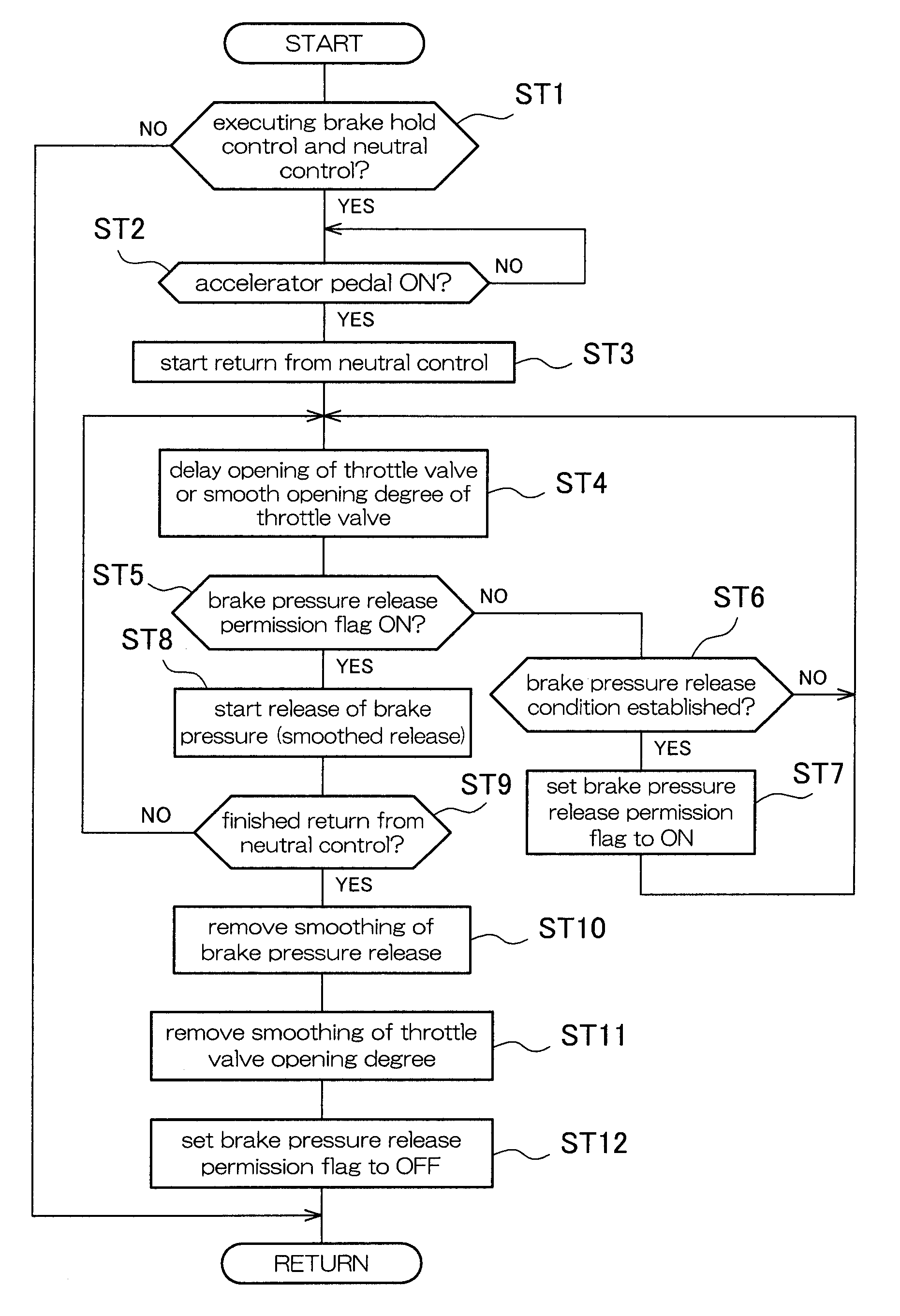
[0020]The present invention was made in consideration of such circumstances, and it is an object thereof to provide a vehicle control apparatus that, in a circumstance in which a neutral control is being executed during execution of a brake hold control, when returning from the neutral control in response to a demand to start forward vehicle movement, is capable of suppressing a shock when returning from the neutral control.
[0021]The present invention provides a control apparatus for a vehicle comprising an internal combustion engine and an automatic transmission having a forward clutch that is engaged when the vehicle starts moving forward, the vehicle control apparatus including a neutral control unit that executes a neutral control that sets power transmission of the forward clutch to not more than a predetermined value while the vehicle is stopped, a brake hold control unit that executes a brake hold control that preserves braking force of the vehicle regardless of operation of a brake pedal, and an engine torque control unit that, in a circumstance in which the neutral control is being executed during execution of the brake hold control, when there has been a demand to start forward vehicle movement, starts a return from the neutral control, and when returning from the neutral control, smoothly increases the engine torque of the internal combustion engine regardless of an accelerator opening degree.
[0022]According to the present invention, it is possible to suppress an early increase in the engine torque of the internal combustion engine when returning from the neutral control, so controllability of the forward clutch of the automatic transmission is improved. Thus, it is possible to suppress a shock when returning from the neutral control.
[0023]In the present invention, it is preferable that the start of increasing the engine torque of the internal combustion engine is delayed for a predetermined length of time after the point in time that there was a demand to start forward vehicle movement. Also, it is preferable that a slope of the increase in the engine torque of the internal combustion engine (for example, a slope of the increase in a throttle opening degree) is limited to not more than a predetermined value. By adopting such a configuration, it is possible to more effectively suppress a shock when returning from the neutral control.
[0024]In the present invention, it is preferable to preserve braking force of the vehicle when returning from the neutral control, thus preventing backward movement of the vehicle when returning from the neutral control. Also, it is preferable that during the return from the neutral control, braking force is smoothly released by limiting a slope of release of braking force to not more than a predetermined value.
[0025]In the present invention, it is preferable to start releasing braking force at a point in time delayed for a predetermined length of time from the point in time that there was a demand to start forward vehicle movement (the point in time of starting the return from the neutral control). By, in this manner, not starting the release of braking force immediately after starting the return from the neutral control, but rather, starting to release braking force at a point in time that a predetermined length of time has passed since starting the return, it is possible to preserve brake pressure until the forward clutch has adequate engaging force to prevent backward vehicle movement, and thus it is possible to more reliably prevent backward movement when the vehicle begins moving forward on a sloped road (when ascending).

Problems solved by technology

However, this phenomenon is not wanted when it is desired to maintain a stopped state of the vehicle, and in this case, creeping force is suppressed by operating the brakes of the vehicle.
That is, the creeping force of the engine is suppressed by the braking force, and there is the problem that to that extent, the engine fuel economy is reduced.
Incidentally, when the neutral control is executed during execution of the brake hold control, because it is necessary to return from the neutral control with accelerator pedal ON as a trigger, there is the problem that a shock occurs at the time of return from the neutral control, reducing drivability.
On the other hand, when the brake hold control and the neutral control are executed at the same time (including when the all vehicle speed cruise control is executed), there may be an instance when the driver's foot is removed from the brake pedal while the vehicle is stopped, so it is not possible to use the ordinary trigger “brake pedal OFF” as the trigger for returning from the neutral state.
When, in this manner, the return from the neutral control is performed using accelerator pedal ON (or operation of the resume lever) as a trigger, it is not possible to obtain the brake pedal release time or the like that is present in a return from the ordinary neutral control.
However, because it is difficult to adapt hydraulics of the forward clutch to match the engine torque, which changes variously depending on how the accelerator pedal is depressed, a shock occurs when returning from the neutral control.
When, in this manner, the start of the return from the neutral control and the return from the brake hold control (the start of the release of brake pressure) are performed at the same time, the brake pressure is released earlier than the engagement of the forward clutch of the automatic transmission, so when the vehicle begins moving forward on a sloped road (when ascending), there is a risk that it will not be possible to obtain adequate creeping force, and the vehicle will move backward.

Method used


Image

  • Vehicle control apparatus
  • Vehicle control apparatus
  • Vehicle control apparatus

Examples


Embodiment Construction

[0034]Hereinafter, embodiments of the present invention will be described in detail with reference to the accompanying drawings.

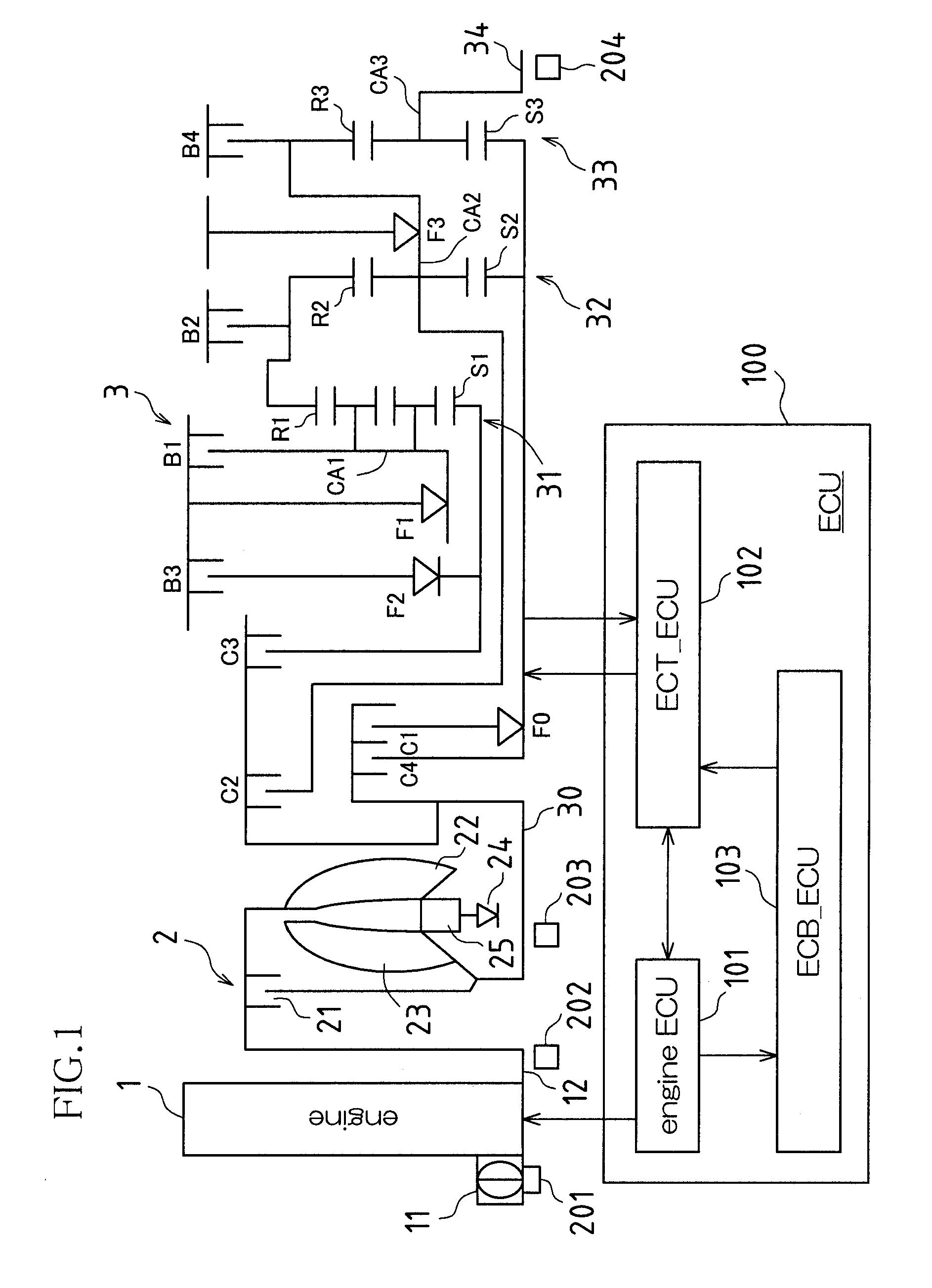
[0035]A powertrain of a vehicle that includes the control apparatus of the present invention will be described with reference to FIG. 1. The control apparatus of the vehicle in this example is realized by a program executed by an ECU (Electronic Control Unit) 100 shown in FIG. 1.

[0036]As shown in FIG. 1, the powertrain of this vehicle is configured from an engine 1, a torque converter 2, an automatic transmission 3, and the ECU 100. Each portion of the engine 1, the torque converter 2, the automatic transmission 3, and the ECU 100 will be described below.

(Engine)

[0037]The amount of air sucked into the engine 1 is adjusted by an electronically controlled throttle valve 11. The throttle valve 11 is capable of electronically controlling a throttle opening degree independent of operation of an accelerator pedal by a driver, and that opening degree (the throttle...


PUM


Abstract

A vehicle control apparatus according to an embodiment of the present invention involves a neutral control unit that executes a neutral control that sets power transmission of the forward clutch to not more than a predetermined value while the vehicle is stopped, a brake hold control unit that executes a brake hold control that preserves braking force of the vehicle regardless of operation of a brake pedal, and an engine torque control unit that, in a circumstance in which the neutral control is being executed during execution of the brake hold control, when there has been a demand to start forward vehicle movement, starts a return from the neutral control, and when returning from the neutral control, smoothly increases the engine torque of the internal combustion engine regardless of an accelerator opening degree.

Description

BACKGROUND OF THE INVENTION[0001]1. Field of the Invention[0002]The present invention relates to a control apparatus for a vehicle equipped with an internal combustion engine (below, also referred to as an engine) and an automatic transmission. More specifically, the present invention relates to a vehicle control apparatus that executes a neutral control that puts an automatic transmission of a stopped vehicle into a neutral state, and a brake hold control that maintains braking force of the vehicle regardless of operation of a brake pedal by a driver.[0003]2. Description of the Related Art[0004]In an engine installed in a vehicle, electronic throttle systems are known in which an actuator is provided that drives a throttle valve provided in an intake path, the electronic throttle system enabling control of a throttle opening degree independent of operation of an accelerator pedal by a driver. In an electronic throttle system, the throttle opening degree is controlled so as to obtai...

Claims


Application Information

Patent Timeline
IPC IPC(8): B60W30/18B60W10/06B60W10/10B60W10/18B60T7/12B60W10/00B60W10/04B60W10/11B60W10/115B60W10/184F02D29/00F02D29/02F02D41/04F16H59/18F16H59/42F16H59/54F16H59/68F16H61/04F16H61/68F16H61/684F16H61/686F16H63/50
CPCB60W10/06B60W10/115B60W10/18F16H2312/02F16H61/20F16H2061/0488B60W30/18027
Inventor KAMISHIMA, HIROFUMIMIZOBUCHI, MASAYASU
Owner TOYOTA JIDOSHA KK
Learn More