
Multi-Component Valve Stems

a valve stem and multi-component technology, applied in the field of valve stems, can solve the problems of reducing the accuracy and reliability of the metered dose dispensing valve comprising such a valve stem, reducing the application of such co-molding, and reducing the accuracy and reliability of the metered dose dispensing valve. , to achieve the effect of enhancing the resistance to leakage, reducing leakage, and reducing the amount of elongated stems

Inactive Publication Date: 2008-05-29
3M INNOVATIVE PROPERTIES CO
View PDF15 Cites 11 Cited by
  • Summary
  • Abstract
  • Description
  • Claims
  • Application Information

AI Technical Summary

Benefits of technology

[0009]Although such co-molding of the elongate stem and sealing elements is advantageous in that it allows the provision of a chemical and / or mechanical bond between the respective components and thereby minimizes leakage, we have found that due to material and / or structural considerations the application of such co-molding is not always feasible or practical. For example, the sealing element may have a complex geometry precluding the application of co-molding, or the desired or needed materials selected for the sealing and elongate stem elements may preclude the use of co-molding. Thus, there is an ongoing need to provide valve stems for metered dose dispensing valves comprising mechanically affixed sealing elements showing a desirably, minimal or no tendency towards leakage in use and thus superior performance properties for use in metered dose dispensing valves for the delivery of medicament.
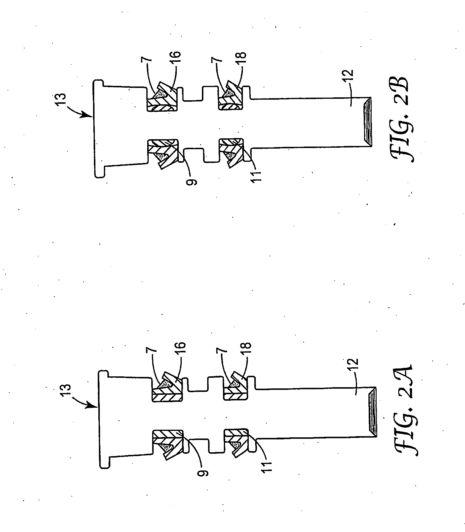
[0010]We have now found that by providing an elastomeric sleeve molded onto the elongate stem element and located, desirably circumferentially, between, at least a portion of the interface between the elongate stem element and the sealing element affixed thereto, a valve stem having enhanced resistance to leakage as well as desirable robustness, e.g. over a typical lifetime-use in a metering valve, can be provided, while at the same time allowing for a broad freedom in material selection and / or structural design for the elongate stem and sealing elements.

Problems solved by technology

In particular, it has been noted that for valve stems having a (e.g. an annular elastomeric) sealing element mechanically affixed onto the elongate stem element, there may be a tendency towards the formation of a leakage path at the interface between the elongate stem and sealing element.
Tendency towards leakage in turn may disadvantageously reduce the accuracy and reliability of the metered dose dispensing valve comprising such a valve stem.
Although such co-molding of the elongate stem and sealing elements is advantageous in that it allows the provision of a chemical and / or mechanical bond between the respective components and thereby minimizes leakage, we have found that due to material and / or structural considerations the application of such co-molding is not always feasible or practical.
For example, the sealing element may have a complex geometry precluding the application of co-molding, or the desired or needed materials selected for the sealing and elongate stem elements may preclude the use of co-molding.

Method used


Image

  • Multi-Component Valve Stems
  • Multi-Component Valve Stems
  • Multi-Component Valve Stems

Examples


Embodiment Construction

[0024]It is to be understood that the present invention covers all combinations of particular and preferred aspects of the invention described herein.

[0025]For a better understanding of the present invention, an exemplary dispensing valve of the prior art, which may advantageously include a valve stem in accordance with the present invention, will be initially described.

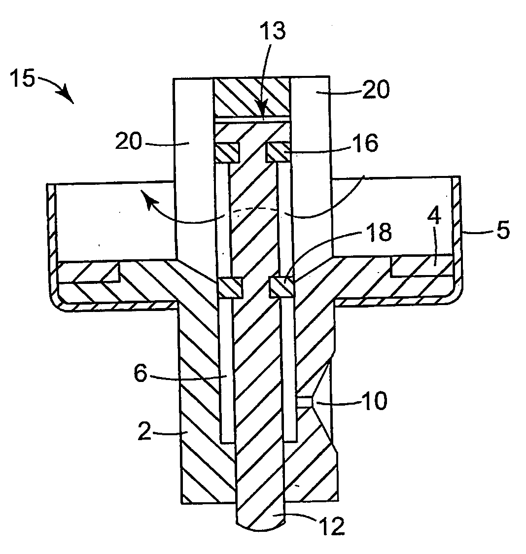
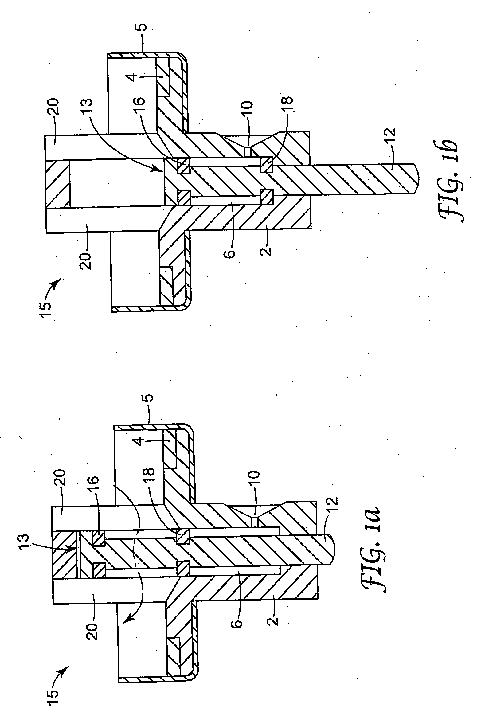
[0026]FIGS. 1a and b illustrate an exemplary shuttle-type metered dose dispensing valve, disclosed in U.S. Pat. No. 5,772,085 and incorporated herein by reference. Referring to FIGS. 1a and b, the valve (15) typically comprises a body (2) having an annular gasket seal (4) for engaging the neck of an aerosol container or vial (not shown) to facilitate a gas-tight seal. The body (2) may be secured to the aerosol container or vial by any suitable means e.g. a conventional outer casing or ferrule (5), which is crimped around the neck of the aerosol container. As can be best seen in FIG. 1b, the body (2) defines a chamber...


PUM

PropertyMeasurementUnit
thicknessaaaaaaaaaa
thicknessaaaaaaaaaa
thicknessaaaaaaaaaa

Abstract

A valve stem (13) for use with a metering valve, said valve stem (13) comprising an elongate stem element (12) having an elastomeric sleeve (9) molded onto at least a portion thereof and a sealing element (16) having an inner surface (7), said sealing element (16) being affixed onto the elongate stem element (12), such that at least a portion of the inner surface (7) of the sealing element (16) is overlying at least a portion of the elastomeric sleeve (9); as well as methods of manufacturing such a valve stem.

Description

FIELD[0001]The present invention relates to valve stems for metered dose dispensing valves for dispensing metered volumes of a pressurized aerosol formulation, in particular medicinal aerosol formulations, from an aerosol container.BACKGROUND[0002]Metering valves are particularly useful for administering medicinal formulations that include a liquefied gas propellant and are delivered to a patient in an aerosol for inhalation, nasal, or sublingual administration.[0003]Medicinal aerosol formulations generally comprise medicament, one or more propellants, (e.g. chlorofluorocarbons and more recently hydrogen-containing fluorocarbons, such as 1,1,1,2-tetrafluoroethane (HFA 134a) and 1,1,1,2,3,3,3-heptafluoropropane (HFA 227)) and possibly excipients, such as surfactant and / or a solvent, such as ethanol.[0004]When administering medicinal formulations, a dose of formulation sufficient to produce the desired physiological response is delivered to the patient. The proper predetermined amount...

Claims


Application Information

Patent Timeline
Patent Type & Authority Applications(United States)
IPC IPC(8): B65D83/14B29C45/00F16K21/16F16K51/00B29C45/14B29C45/16
CPCB29C45/14336B29C45/1671B29C45/1676Y10T29/4941B29K2221/003B65D83/54B29C2045/14459
Inventor PURKINS, GRAHAM R.
Owner 3M INNOVATIVE PROPERTIES CO
Learn More