
Heart rate demodulation of periodic movement in ultrasound data for object identification

Inactive Publication Date: 2008-05-22
GENERAL ELECTRIC CO
View PDF8 Cites 60 Cited by
  • Summary
  • Abstract
  • Description
  • Claims
  • Application Information

AI Technical Summary

Benefits of technology

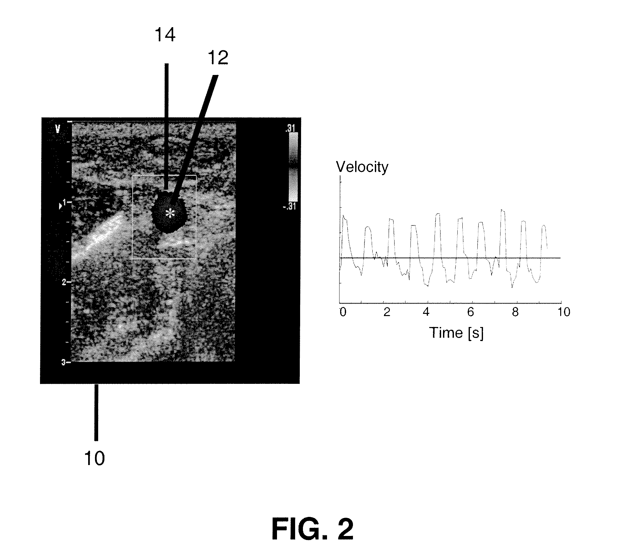
[0003]One or more embodiments of the systems and methods are generally designed to optimize blood flow data collected by a medical ultrasound scanner wherein the technical effect is to identify blood vessels and to enhance images of blood vessels. Such systems and methods provide improved visualization of the vessels allowing vessels to be more easily identified from the surrounding tissue. Some of the embodiments of the systems and methods enhance the signals from pulsating blood flow to facilitate identification of the vessels. The systems and methods use data of the subject's heart rate to effectively remove the periodic variation in the blood velocities and to suppress components of the blood flow signal that differ from the heart rate. The resulting processed data can then be used to automatically detect one or more vessels and / or to enhance the display an image of the vessel, for example, in a display provided in an ultrasound system.
[0004]The ability to measure blood flow both non-invasively and in real-time is one of the advantages of medical ultrasound. By increasing the strength of signal strength from a pulsating artery, the systems and methods of the invention are able improve the robustness of detection systems and allow automated detection of the artery without user intervention. The heart rate demodulation embodiments of the methods are generally adapted to use information about the heart rate to enhance the signal in ultrasound data from objects with periodic motion at that same rate. Although one or more embodiments of the methods are provided for automatically detecting objects and for enhancing such objects for display, the invention is not limited to these embodiments. These systems and methods will benefit virtually any application in which identification of vessels or other similar objects is desired or required.

Problems solved by technology

Previous attempts to use ultrasound data to detect blood vessels were insufficient.

Method used


Image

  • Heart rate demodulation of periodic movement in ultrasound data for object identification
  • Heart rate demodulation of periodic movement in ultrasound data for object identification
  • Heart rate demodulation of periodic movement in ultrasound data for object identification

Examples


Embodiment Construction

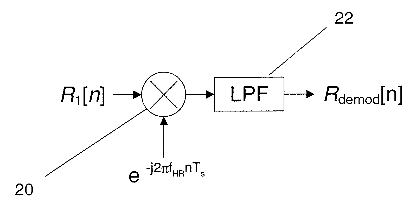
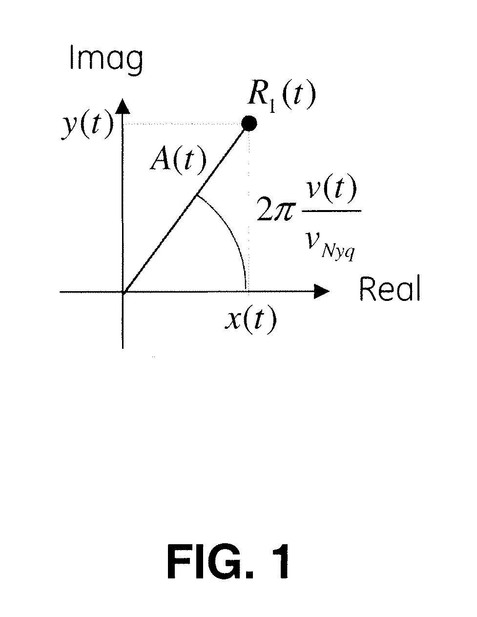
[0022]The heart rate demodulation embodiment of the methods and systems may be applied directly to the raw samples from a standard Doppler color flow acquisition, generally referred to as the complex autocorrelation function at a single frame lag. Components of the blood flow signal at frequencies that differ from the heart rate are suppressed by applying digital filtering techniques directly to the complex autocorrelation samples. The heart rate can be obtained from another modality (such as ECG or pulse oximetry), directly from the ultrasound data itself, or from nominal values for the physiological range. The implementation used in the development of the invention included complex demodulation of the autocorrelation samples followed by a lowpass filter. The demodulation step converts the velocities pulsating at the heart rate to constant signal levels and the lowpass filter attenuates components of the velocity varying at frequencies other than the heart rate, including the harmo...


PUM


Abstract

A system and method for enhancing and displaying a target object, that generally comprises: a processor that demodulates the rate of movement of the target object to produce a demodulated signal; computes the power of the demodulated signal; creates an image sequence, based on the power of the demodulated signal, that comprises the enhanced periodic motion pixels; and forms an image sequence of the enhanced periodic motion pixels to form an image display of at least the target object; and an image display device to display the target object.

Description

BACKGROUND[0001]The invention relates generally to systems and method for enhancing movement related data to detect objects such as blood vessels.[0002]Doppler processing techniques are commonly used in medical ultrasound machines for obtaining velocity information from moving objects. The velocity measured using ultrasound Doppler techniques is the radial component of the velocity directed toward or away from the ultrasound transducer. Two common modes are continuous wave (CW) and pulsed wave (PW) Doppler acquisitions. One advantage of the pulsed wave acquisition is the ability to produce velocities estimates at multiple depths along the beam direction locations allowing a two-dimensional image of the velocities to be formed. The pulsed wave data acquisition consists of transmitting a series of ultrasound pulses at a regular rate, referred to as the pulse repetition rate (PRF), in a given direction. For each transmitted pulse, the RF waveform of the returning echoes is collected as...

Claims


Application Information

Patent Timeline
IPC IPC(8): A61B8/00G06F17/15
CPCA61B8/02A61B8/488A61B8/06
Inventor DENTINGER, AARON MARK
Owner GENERAL ELECTRIC CO
Learn More