
Mechanical connection for transferring forces while providing insulation

a technology of mechanical connection and insulation, which is applied in the direction of mechanical apparatus, press ram, shaping tools, etc., can solve the problems of mechanical deformation of parts, tension and deformation, and unstable situation

Inactive Publication Date: 2008-05-22
AMADA EURO
View PDF6 Cites 5 Cited by
  • Summary
  • Abstract
  • Description
  • Claims
  • Application Information

AI Technical Summary

Benefits of technology

[0016]A first object of the present invention is to provide a mechanical connection device between a moving member and the moving end of a drive device that is liable to rise in temperature, which device enables the transmission of heat to the moving member to be eliminated or to be reduced very considerably, while nevertheless enabling a large force to be transmitted between the drive device and the moving member.
[0020]It will be understood that interposing the thermal insulator element in the connection device between the moving end of the drive device and the moving member makes it possible to reduce very considerably the heat flux flowing between the drive device and the moving member, thus making it possible to reduce very considerably the phenomena of thermal expansion in the moving member.

Problems solved by technology

This situation may be unstable over time if the transmission of energy through the contact surface(s) is not constant, if ambient temperature is not constant, or if the heat dissipated through the set of contacting surfaces is less than that transmitted by the heating surface(s).
Regardless of whether the thermal expansion is free or involves internal thermal tensions, the result is mechanical deformation of the part.
This situation is created by the fact that even though the local heating surface areas are very small, they create local thermal tensions and deformations that are strong and that deform zones remote from the heating surfaces by a “lever arm” system, even when those zones are themselves subjected to little heating.

Method used


Image

  • Mechanical connection for transferring forces while providing insulation
  • Mechanical connection for transferring forces while providing insulation
  • Mechanical connection for transferring forces while providing insulation

Examples


Embodiment Construction

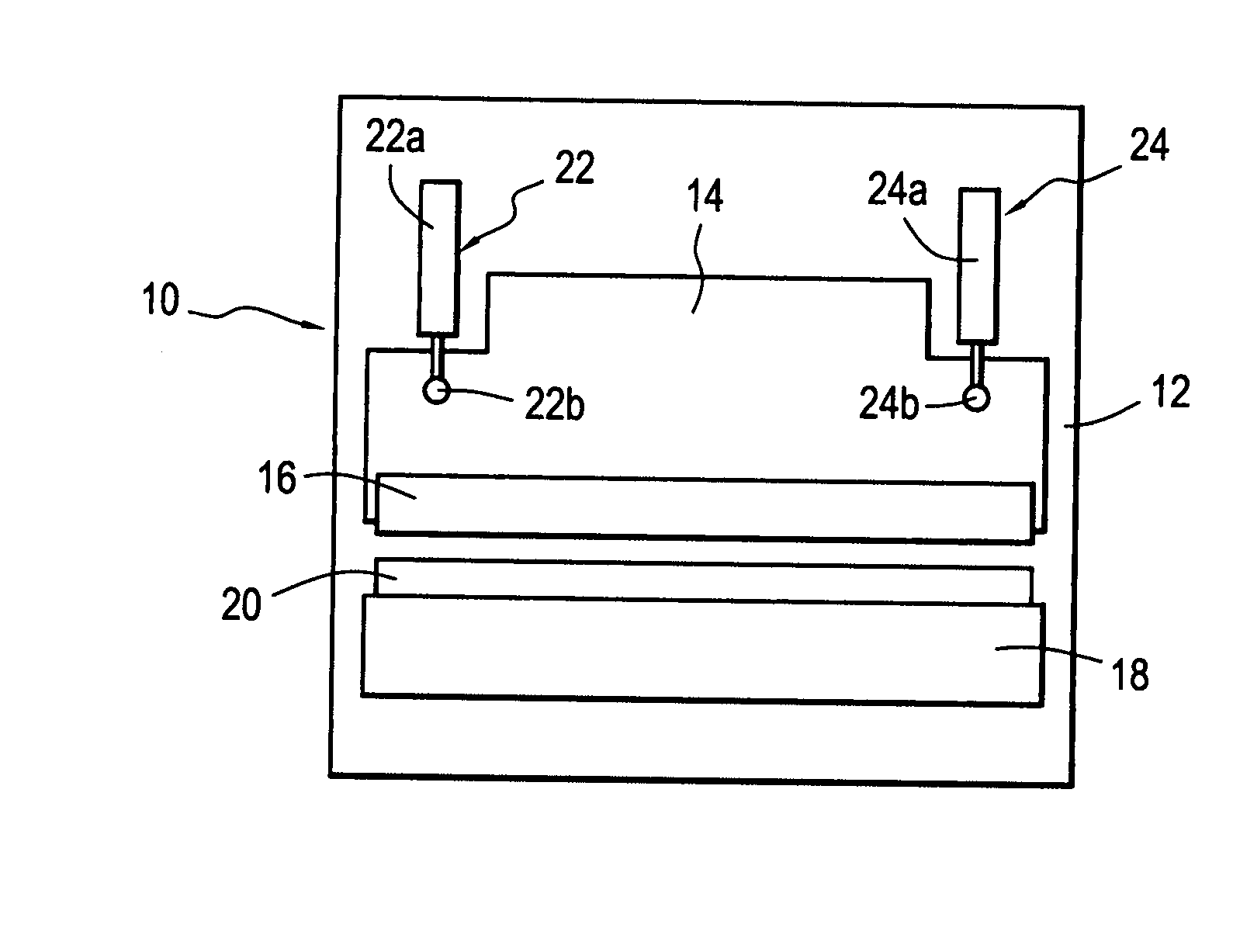
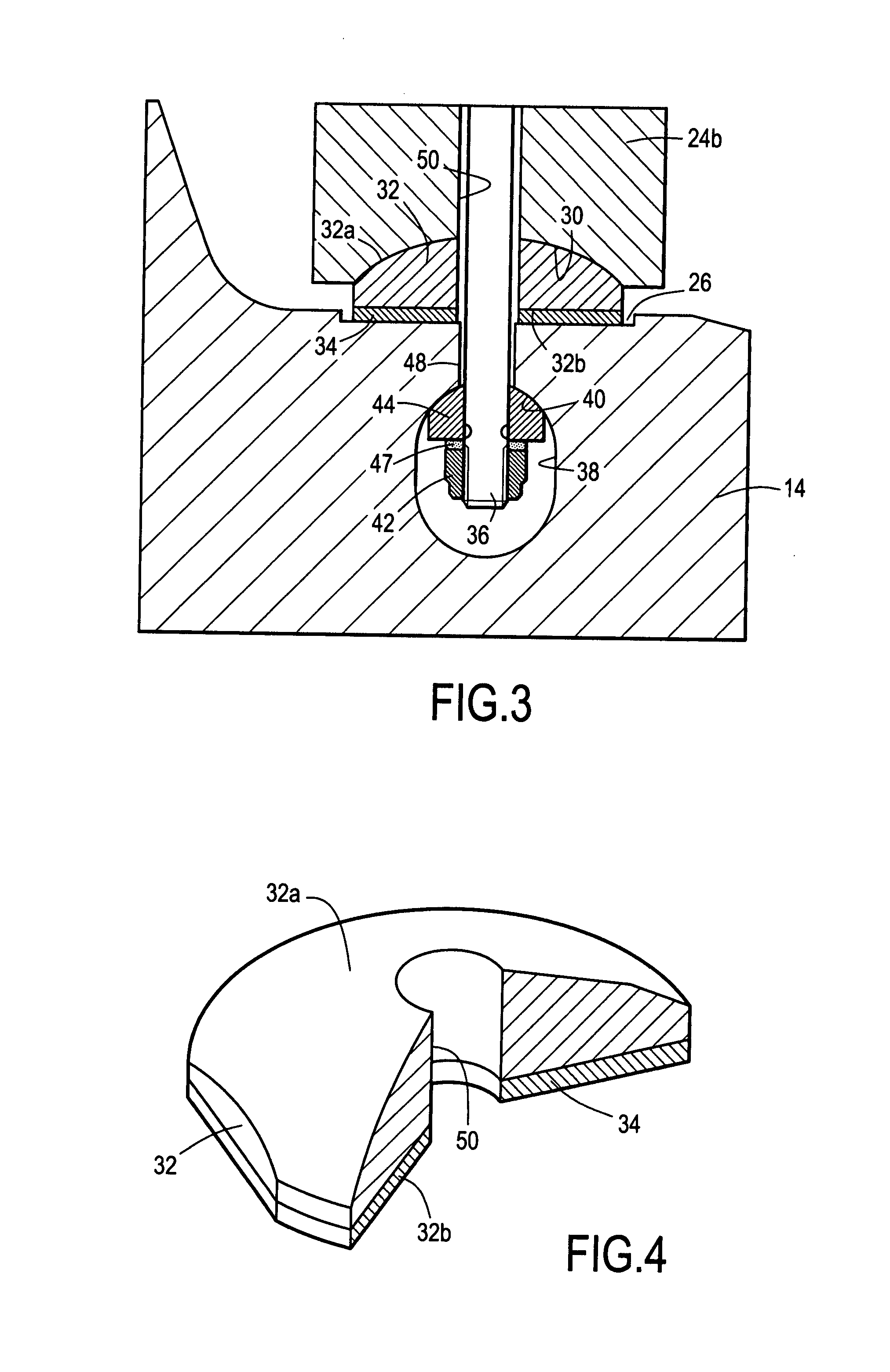
[0032]With reference now to FIGS. 3 and 4, there follows a description of a preferred embodiment of the mechanical connection between the end of the piston of a hydraulic ram and the top die of a press brake of the type described above. Naturally, the description merely constitutes one example of how the mechanical connection device of the invention can be used, and numerous other applications could be envisaged.

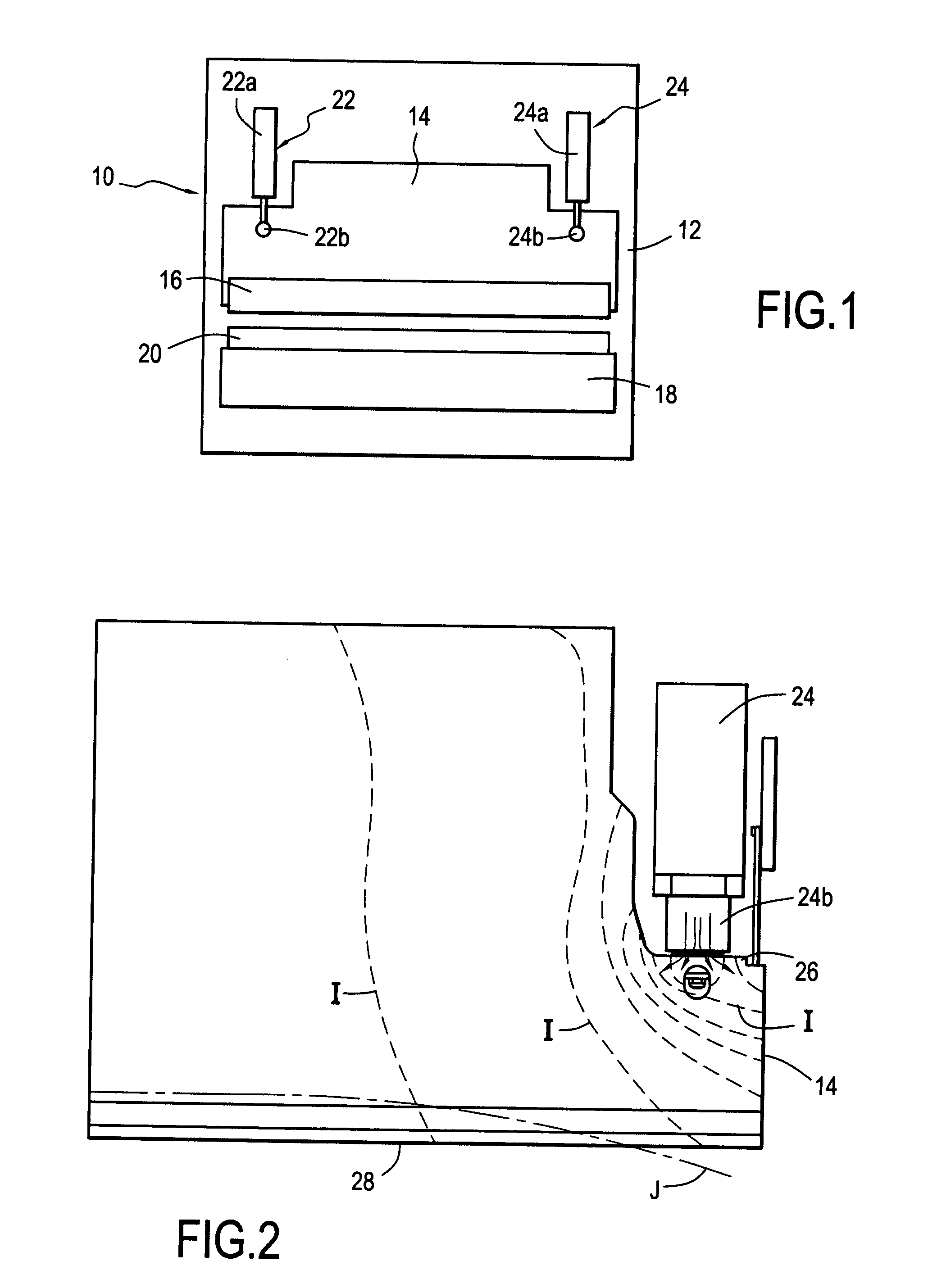
[0033]In FIG. 3, there can be seen a portion of the top die 14 of the press brake of FIGS. 1 and 2, together with the piston 24b of the actuator 24 and the face 26 of the top die against which the piston of the ram is to apply a force. In this embodiment, the end of the piston 24b is partially in the form of a concave spherical cap 30 constituting a ball-joint surface. Between the end of the piston of the ram 24b and the surface 26, there are interposed firstly an insulator element 32 and secondly a metal element 34. The insulator element 32 has a top face 32a in the form of...


PUM

PropertyMeasurementUnit
temperaturesaaaaaaaaaa

Abstract

The invention relates to a connection device between a moving member and the moving end of a drive device. It comprises:a mechanical connection element in contact with said moving member; anda thermal insulator element interposed between said mechanical connection element and said end of the drive device, whereby the heat produced by said drive device is substantially not transmitted to said moving member.The invention is applicable to making press brakes.

Description

[0001]The present invention provides a mechanical connection device between a moving member and the moving end of a drive device, and more particularly such a mechanical connection device that serves substantially to prevent the transmission of heat from the drive device to the moving member while allowing large forces to be transmitted. The invention also relates to a drive system using such a mechanical connection device and to a press brake for folding sheet metal and including such a drive system.BACKGROUND OF THE INVENTION[0002]It is well known that when two parts presenting relatively high coefficients of thermal expansion are in intimate contact, and one of the elements in contact is at a temperature higher than ambient temperature, then heat will propagate to the other part, thereby causing said other part to expand thermally.[0003]When the part is of dimensions that are large compared with the contacting surfaces that constitute the heating points, the temperature at each p...

Claims


Application Information

Patent Timeline
Patent Type & Authority Applications(United States)
IPC IPC(8): B21D5/04
CPCB30B15/068F16C11/0661B30B15/34
Inventor HANSEN, BJARNE
Owner AMADA EURO
Learn More