
Storage controller, and logical volume formation method for the storage controller

a storage controller and logical volume technology, applied in the direction of memory address/allocation/relocation, instruments, error detection/correction, etc., can solve the problems of inability to improve and neither of the above conventional technologies considers virtual construction of one logical volume from a plurality of logical storage devices. to achieve the effect of improving responsive performance and improving responsive performance at the time of random access

Active Publication Date: 2008-05-15
GOOGLE LLC
View PDF3 Cites 23 Cited by
  • Summary
  • Abstract
  • Description
  • Claims
  • Application Information

AI Technical Summary

Benefits of technology

[0015]The present invention is contrived in view of the above problems, and an object is to provide a storage controller, which is capable of appropriately selecting, based on the type of access pattern and a performance indicator set in a logical volume beforehand when configuring the logical volume by using a plurality of logical storage devices, a physical storage device provided with the logical storage devices, and to provide a logical volume formation method for the storage controller. Other object of the present invention is to provide a storage controller, which distributes to allocate a plurality of logical storage devices associated with a logical volume to a plurality of physical storage devices to attempt to even the loads in the physical storage devices so that the responsive performance at the time of random access can be improved, and to provide a logical volume formation method for the storage controller. In addition to the above objects, yet other object of the present invention is to provide a storage controller, which allocates logical storage devices of the first order to separate physical storage devices as much as possible to attempt to disperse the loads in the physical storage devices so that the responsive performance can be improved, and to provide a logical volume formation method for the storage controller. Yet other objects of the present invention will become clear from the following descriptions of embodiments.
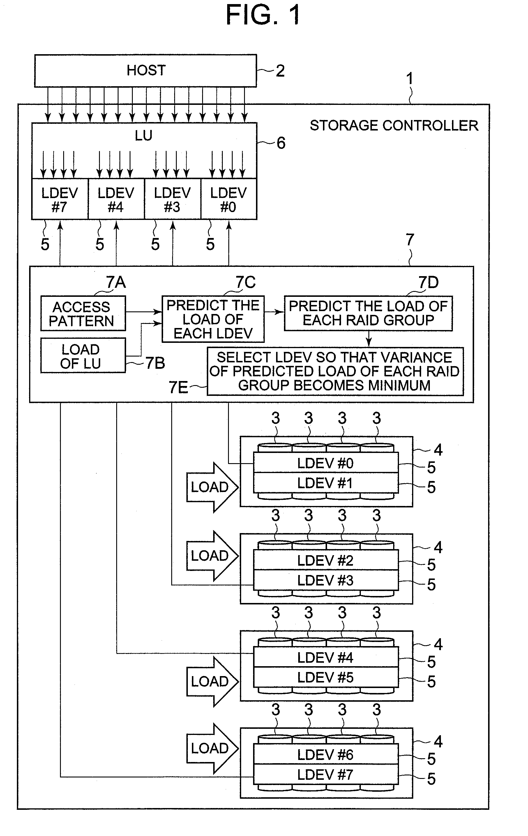
[0017]The control section can compute a second performance indicator of each of the plurality of predetermined logical storage devices in accordance with the type of access pattern and the first performance indicator, compute a third performance indicator of each of the physical storage devices on the basis of the second performance indicator, and select the physical storage devices to which the plurality of predetermined logical storage devices are allocated, so that variances of the third performance indicators becomes small.
[0019]The control section can compute a second performance indicator for each of the plurality of predetermined logical storage devices in accordance with the type of access pattern and the first performance indicator, compute a third performance indicator for each of the physical storage devices on the basis of the second performance indicator, and select the physical storage devices to which the plurality of predetermined logical storage devices are allocated, so that a variance of the difference between the third performance indicator and a preset maximum value becomes small.

Problems solved by technology

However, neither one of the above conventional technologies considers virtual construction of one logical volume from a plurality of logical storage devices.
Each of the above conventional technologies lacks consideration of the random access in particular.
Therefore, responsive performance at the time of a random access cannot be improved by only determining the destination to allocate a logical storage device in the case of only the sequential access, or determining the destination to allocate a logical storage device based on the access frequency.

Method used


Image

  • Storage controller, and logical volume formation method for the storage controller
  • Storage controller, and logical volume formation method for the storage controller
  • Storage controller, and logical volume formation method for the storage controller

Examples


embodiment 1

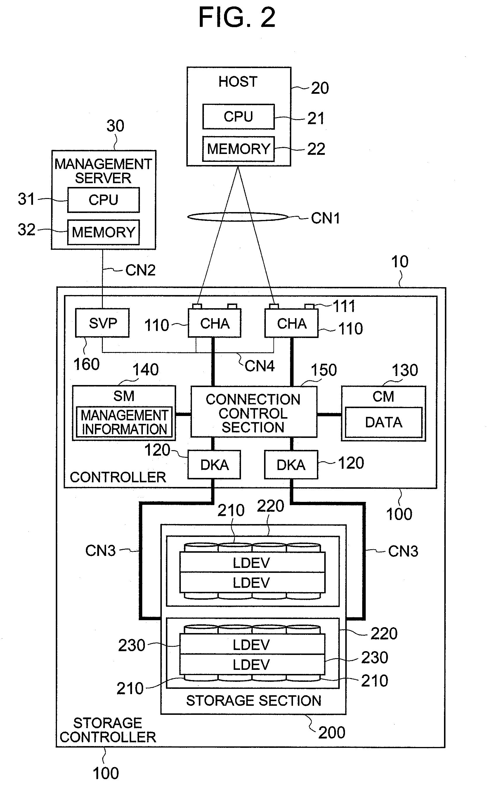
[0099]FIG. 2 is a block diagram showing a configuration of the storage controller according to the present embodiment. A host 20 is a computer apparatus having information processing resources such as a CPU (Central Processing Unit) 21 and a memory 22, and is constituted as, for example, a personal computer, work station, server computer, main frame computer, or the like.

[0100]The host 20 has a communication control section for accessing a storage controller 10 via a communication network CN1, and an application program such as database software.

[0101]As the communication network CN1, for example, a LAN (Local Area Network), SAN (Storage Area Network), the Internet, a private line, a public line, or the like can be used appropriately according to circumstances. Data communication using a LAN is performed in accordance with, for example, a TCP / IP protocol. When the host 20 is connected to the storage controller 10 via a LAN, the host 20 specifies a file name to request input / output o...

embodiment 2

[0241]The second embodiment of the present invention is described with reference to FIG. 34 and FIG. 35. The following examples including the present invention are same as the modifications of the above-described first embodiment. In the present embodiment, the agent 300 and the like are provided inside the storage controller 10, and the storage controller 10 itself automatically executes the processing of associating the logical volume 102 with the logical devices 230.

[0242]FIG. 34 is an explanatory diagram which schematically shows the configuration of the storage controller 10 according to the present embodiment. The controller 100 is provided with the agent 300, configuration management section 310 and performance management section 320. Furthermore, the tables T10 through T40 are stored in the shared memory 140. It should be noted that the tables T10 through T40 can be stored in the cache memory 130 as well.

[0243]The user can set various conditions for associating the logical v...

embodiment 3

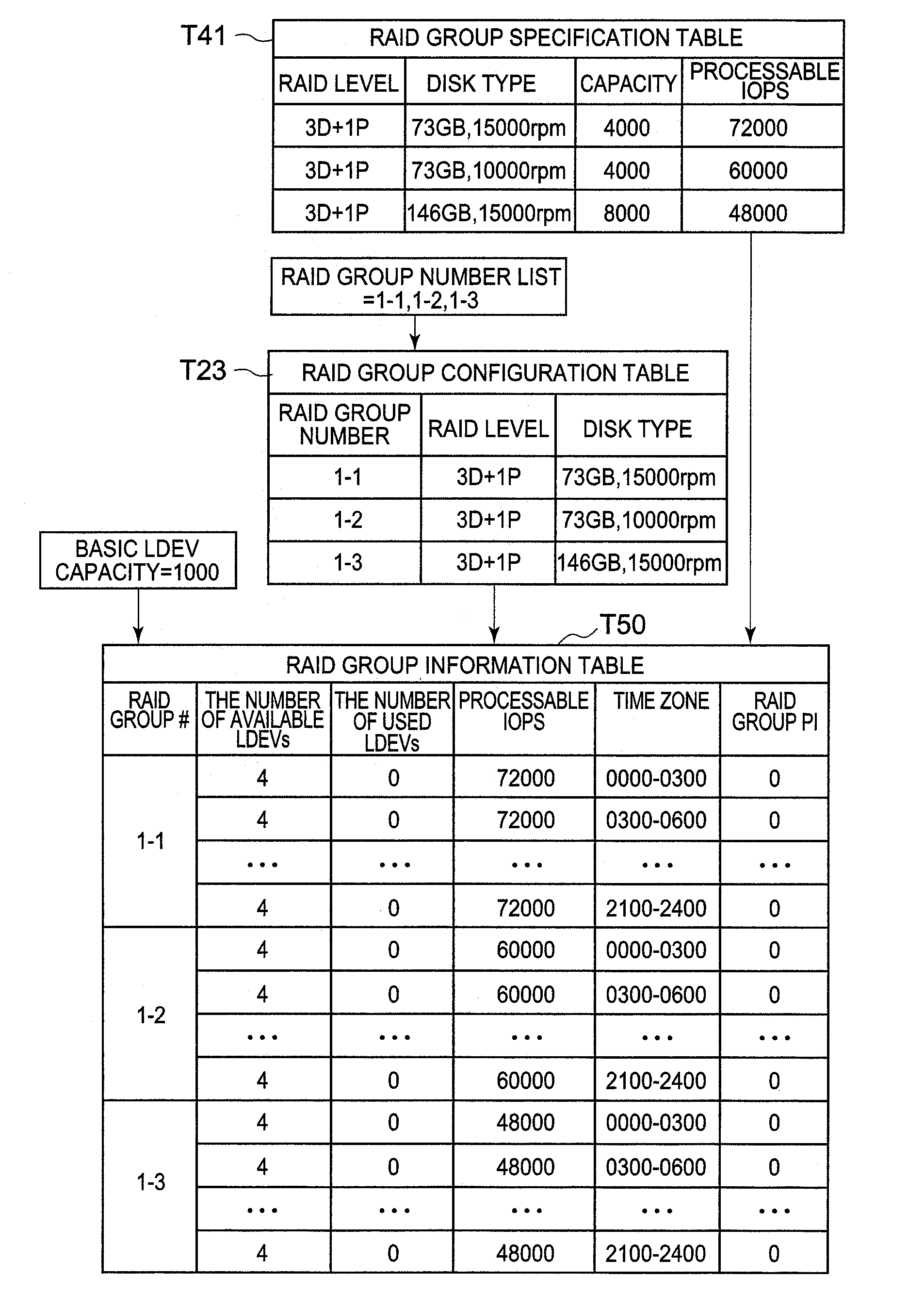
[0248]The third embodiment is described with reference to FIG. 36. The present embodiment suggests another method of computing a variance. FIG. 36 is an explanatory diagram showing the method of computing a variance. In the present embodiment, an indicator called “excess IOPS” is used in place of the RAID group performance indicator shown in the equation 2 above.

[0249]The excess IOPS is a value obtained by subtracting the RAID group performance indicator from the value of the maximum IOPS which can be processed by each RAID group 220 (excess IOPS=processable IOPS−RAID group performance indicator (RAID group PI)). Specifically, the excess IOPS is an indicator that indicates an allowance in the processing of the RAID group 220. In the present embodiment variances are computed according to the following equation 3.

Variance=(1 / number of all records)×Σ(excess IOPS−average value)̂2  (Equation 3)

[0250]Then, as with the first embodiment or the second embodiment, the agent 300 determines the...


PUM


Abstract

When associating a plurality of logical devices with one logical volume, the storage controller of the present invention improves the responsive performance thereof by determining the position for allocating the logical devices in accordance with the pattern of access made from the host. One logical volume is constituted by a plurality of logical devices. The control section computes the performance indicator (load) of each logical device in accordance with the pattern of access to the logical volume from the host. The control section computes the performance indicator of each RAID group for the case where each logical device is allocated on the basis of the performance indicator of each logical device. The control section determines a RAID group to allocate each logical device, so that the variance of the performance indicator of the RAID group becomes minimum.

Description

CROSS-REFERENCE TO RELATED APPLICATION[0001]This application relates to and claims priority from Japanese Patent Application No. 2006-304526 filed on Nov. 9, 2006, the entire disclosure of which is incorporated herein by reference.BACKGROUND OF THE INVENTION[0002]1. Field of the Invention[0003]The present invention relates to a storage controller and a logical volume formation method for the storage controller.[0004]2. Description of the Related Art[0005]In the government, the public office, local governments, companies, educational institutions and the like, for example, relatively large storage systems are used to manage data, in order to handle large amounts of various data. Such storage systems are constituted by a storage controller such as a disk array device or the like. A disk array device is configured by disposing a number of disk drives in the form of array, and provides a storage region based on, for example, RAID (Redundant Array of Independent Disks).[0006]A plurality ...

Claims


Application Information

Patent Timeline
Patent Type & Authority Applications(United States)
IPC IPC(8): G06F12/02
CPCG06F3/0611G06F3/0631G06F3/0653G06F3/0665G06F11/3485G06F11/1076G06F11/3419G06F11/3447G06F3/0689G06F2201/885
Inventor AOKI, YOSHITAKA
Owner GOOGLE LLC
Learn More