Method and Device for Sealing

a magnetic hysteresis and sealing technology, applied in the field of methods and devices for magnetic hysteresis sealing, can solve problems such as loss of magnetic hysteresis, achieve high speed, prevent overheating of packaging material laminates, and save energy

Inactive Publication Date: 2008-05-15
TETRA LAVAL HLDG & FINANCE SA
View PDF7 Cites 1 Cited by
  • Summary
  • Abstract
  • Description
  • Claims
  • Application Information

AI Technical Summary

Benefits of technology

[0012]An object of the invention has been to find an efficient and practical way of using magnetic hysteresis for sealing packaging material laminates in a high speed packaging machine. Another object is to achieve a sealing technique by which overheating of the packaging material laminates is prevented.
[0014]Applying a magnetic field to packaging material laminates comprising magnetizable particles is effective and has been found to be an equally good sealing technique compared to the techniques normally used in packaging machines. Further, the use of magnetic hysteresis sealing prevents overheating of the packaging material laminates. This is due to the fact that the ferromagnetic properties of the magnetizable particles slowly start to cease when the laminates are heated. Thus, during temperature raise the hysteresis loop area will decrease. Consequently, the energy generated in the material will also decrease. Such energy decrease will in turn also decrease the heat generated in the material. Accordingly, since the heat is decreasing, the magnetization of the particles can increase again, and can increase until the heat generated in the material makes it start decreasing again. Thus, a system has been formed in which the temperature will fluctuate within a certain range, but will never raise above it. By a suitable choice of magnetizable particles, particle amounts and packaging material laminate structures the risk of overheating is eliminated.
[0015]In a presently preferred embodiment the method comprises the step of providing the alternating magnetic field in such a way that the main direction of the magnetic field lines is substantially parallel with a plane constituting the first packaging material laminate. In this way a magnetic field is generated in the sealing zone which magnetic field is sufficient to achieve a sealing time and a frequency that are industrially applicable in a high speed packaging machine. It has been found that the area of a hysteresis loop where the main direction of the magnetic field lines is substantially parallel with the laminate plane is substantially equal to the area of a hysteresis loop where the main direction of the magnetic field lines is substantially perpendicular to the laminate plane. The difference is that the magnetic field needed to obtain the area in the perpendicular case is higher, in fact almost twice as high. Thus, the parallel case would seem more efficient.
[0018]In a further presently preferred embodiment the method comprises the step of enhancing said magnetic field by using an electrically conducting anvil. In yet a further embodiment the method comprises the step of providing said anvil opposed to the sealing jaw, the anvil being able to induce a current in response to the current in the sealing jaw, thereby generating a magnetic field enhancing the field generated by the sealing jaw. The parallelism of the magnetic field lines is increased and a stronger magnetic field can be obtained without having to increase the current supplied to the inductor of the sealing jaw.
[0022]In another presently preferred embodiment the anvil is electrically conducting anvil and provided to enhance said magnetic field. Said anvil is provided with a conductor adapted to induce a current in response to the current in the sealing jaw, thereby generating a magnetic field enhancing the magnetic field generated by the sealing jaw.

Problems solved by technology

These objects have been achieved by a method comprising providing an alternating magnetic field to the laminates in a sealing zone, thereby generating magnetic hysteresis losses in the laminate comprising the magnetizable particles, which losses create heat substantially melting the sealable layer in the sealing zone, and applying a sealing pressure to the first and second laminate, which pressure causes the first and second laminate to be pressed together in the sealing zone, thereby sealing the laminates to each other.

Method used


Image

  • Method and Device for Sealing
  • Method and Device for Sealing
  • Method and Device for Sealing

Examples


Embodiment Construction

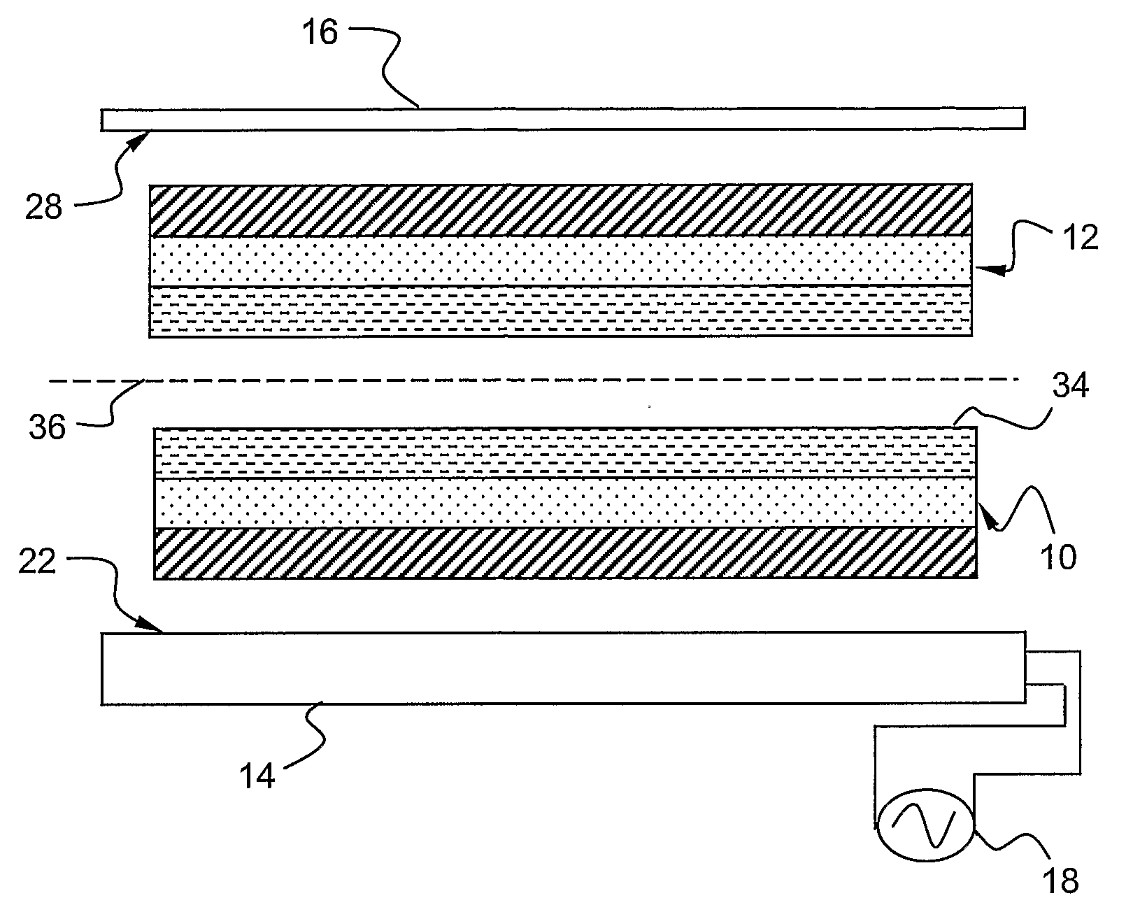
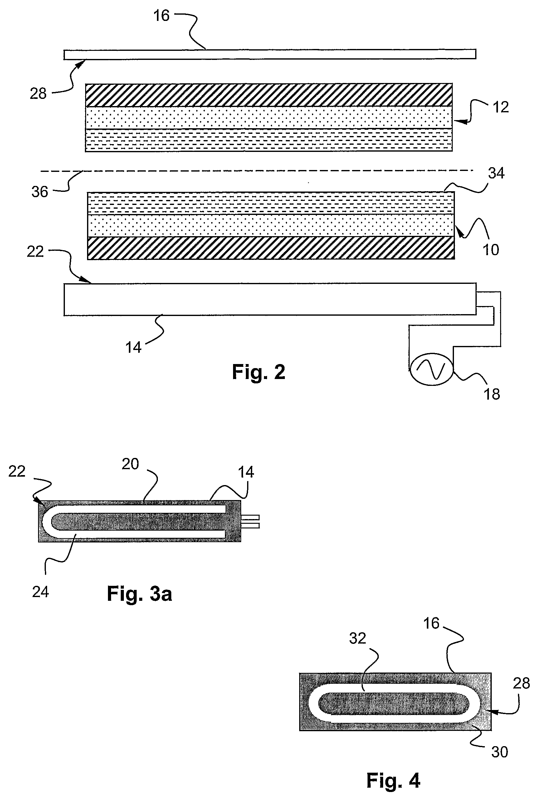
[0035]FIG. 2 shows a presently preferred embodiment of the invention. A first and a second packaging material laminate 10, 12 to be sealed together in a joint by means of a sealing jaw 14 and an anvil 16. In the joint shown the two laminates are abutting each other with their inside surfaces facing each other. In this presently preferred embodiment the sealing jaw 14 is an inductor similar to the ones used for induction sealing (where the laminate comprises aluminum foil that generate heat). The inductor 14 is here coupled to an alternating current supply 18. The alternating current is preferably in the range of 75-300 A and the power needed from the power supply is a few kW. A preferred interval is 2-10 kW. The frequency is preferably in the MHz range, and a preferred frequency interval is 0.5-5 MHz. A most preferred interval is 1-4 MHz. The frequencies that are prohibited for common use due to authority regulations are of course, in practice, excluded from said intervals.

[0036]The...


PUM

PropertyMeasurementUnit
frequencyaaaaaaaaaa
frequencyaaaaaaaaaa
mean sizeaaaaaaaaaa

Abstract

The present invention refers to a method for sealing a first packaging material laminate (10) to a second packaging laminate (12), at least the first laminate (10) comprising at least one layer of magnetizable particles and a sealable layer (34). The method is characterized in facing the sealable layer (34) towards the second laminate (12), providing an alternating magnetic field to the laminates in a sealing zone, thereby generating magnetic hysteresis losses in the laminate (10) comprising the magnetizable particles, which losses create heat substantially melting the sealable layer (34) in the sealing zone, and applying a sealing pressure to the first and second laminate (10, 12), which pressure causes the first and second laminate (10, 12) to be pressed together in the sealing zone, thereby sealing the laminates (10, 12) to each other. The invention also relates to a device for carrying out the method.

Description

THE FIELD OF INVENTION[0001]The present invention refers to a method and a device for magnetic hysteresis sealing of a packaging material laminate comprising at least one layer comprising magnetizable particles.BACKGROUND OF THE INVENTION[0002]In the international patent publication WO 03 / 095198, which is hereby incorporated by reference, a packaging material laminate is described which comprises at least one layer comprising magnetizable particles. The laminate is of the type used for manufacturing of for example liquid food packages, and generally comprises a layer of paper or carton, layers of plastic and barriers, such as for example oxygen barriers. One of the outer layers is normally a sealable layer of a thermoplastic material which is used when sealing one laminate to another. Using thermoplastic layers is known in the art and will not be further described herein.[0003]The magnetizable particles can for example be magnetite, Fe3O4 and have a mean size of about 0.5 μm. Other ...

Claims


Application Information

Patent Timeline
Patent Type & Authority Applications(United States)
IPC IPC(8): B32B37/26B29C53/38B29C65/36B32B
CPCB29C53/38B29C66/1122B29C66/43B29C66/80B29K2995/0008B29C66/4322B29L2031/712B29L2009/00B29C65/3668B29C65/3612B29C65/00B29C66/49B29C66/723B29C66/72321B29C66/8122B29C66/81262B29C66/81871B29C66/8322B29K2909/02B29K2821/00B29K2905/10
Inventor WIJK, MAGNUSRABE, MAGNUSHOLMSTROM, GERTQVARFORD, MATS
Owner TETRA LAVAL HLDG & FINANCE SA
Why Eureka
Try Eureka