
Downhole measurement of substances in formations while drilling

a technology of formations and substances, applied in the field of downhole measurement, can solve the problems of inability to make allowances for the diffusion of gas within the mud, inaccurate pump rate, and inhomogeneity,

Inactive Publication Date: 2008-05-15
SCHLUMBERGER TECH CORP
View PDF7 Cites 35 Cited by
  • Summary
  • Abstract
  • Description
  • Claims
  • Application Information

AI Technical Summary

Benefits of technology

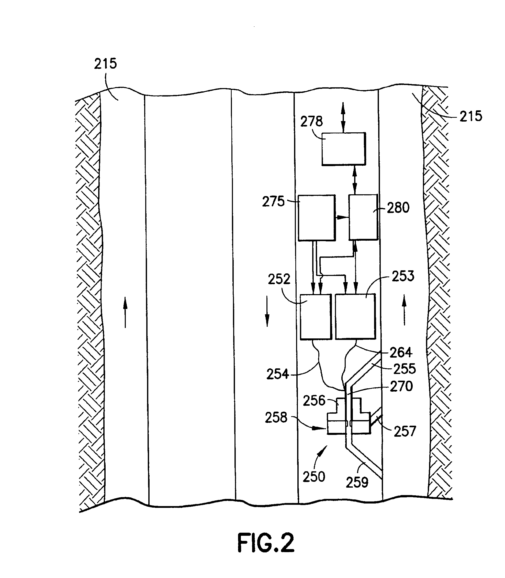
[0011]An embodiment of a form of the invention includes the steps of: obtaining, in the annulus and spaced from the drill bit, a sample of drilling fluid entrained with drilled earth formation cuttings, after its egression from the drill bit; and measuring, downhole, the substance in sampled drilling fluid using a Raman scattering technique. Pulsed Raman scattering can be utilized, with a gated detector, to discriminate fluorescent emission. Also, surface enhanced Raman scattering can be used to advantage.

Problems solved by technology

One problem is depth control; that is, the ability to be able to accurately place the location of an acquired sample.
Given that pump rates are quite inaccurate and the mud properties vary significantly from surface to bottom hole, the depth determination in not reliable.
Moreover, in general, no allowances are made for the diffusion of the gas within the mud or the inhomogeneity in the mixing as the mud travels along the well bore.
A further difficulty is that surface samples tend to be diluted with air and this has to be accounted for in the analysis.
To somewhat improve on surface and laboratory analysis of mud gas and cuttings, there have been proposed downhole analysis for some substances, but with limited capability.
Some proposed techniques require complex downhole processing and / or require conditions that are not practical for obtaining practical information during the drilling process.
This method includes the “washing” of the side wall of the borehole to remove mudcake but apparently does not recognize that adsorbed methane will be removed along with the mudcake.
The prior art acknowledges the difficulties in maintaining equilibrium between borehole fluid and formation and the need to avoid mixing of borehole water from one level to another, but ignores the possibilities of crossflow in the well.

Method used


Image

  • Downhole measurement of substances in formations while drilling
  • Downhole measurement of substances in formations while drilling
  • Downhole measurement of substances in formations while drilling

Examples


Embodiment Construction

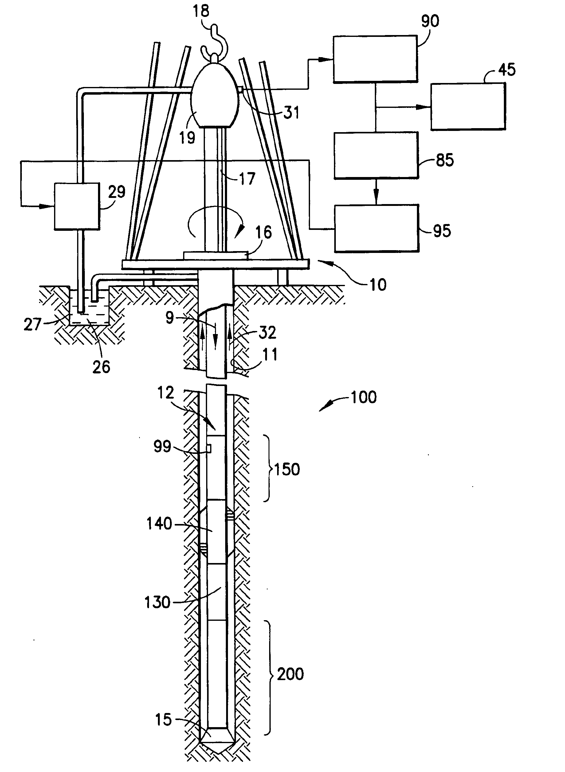
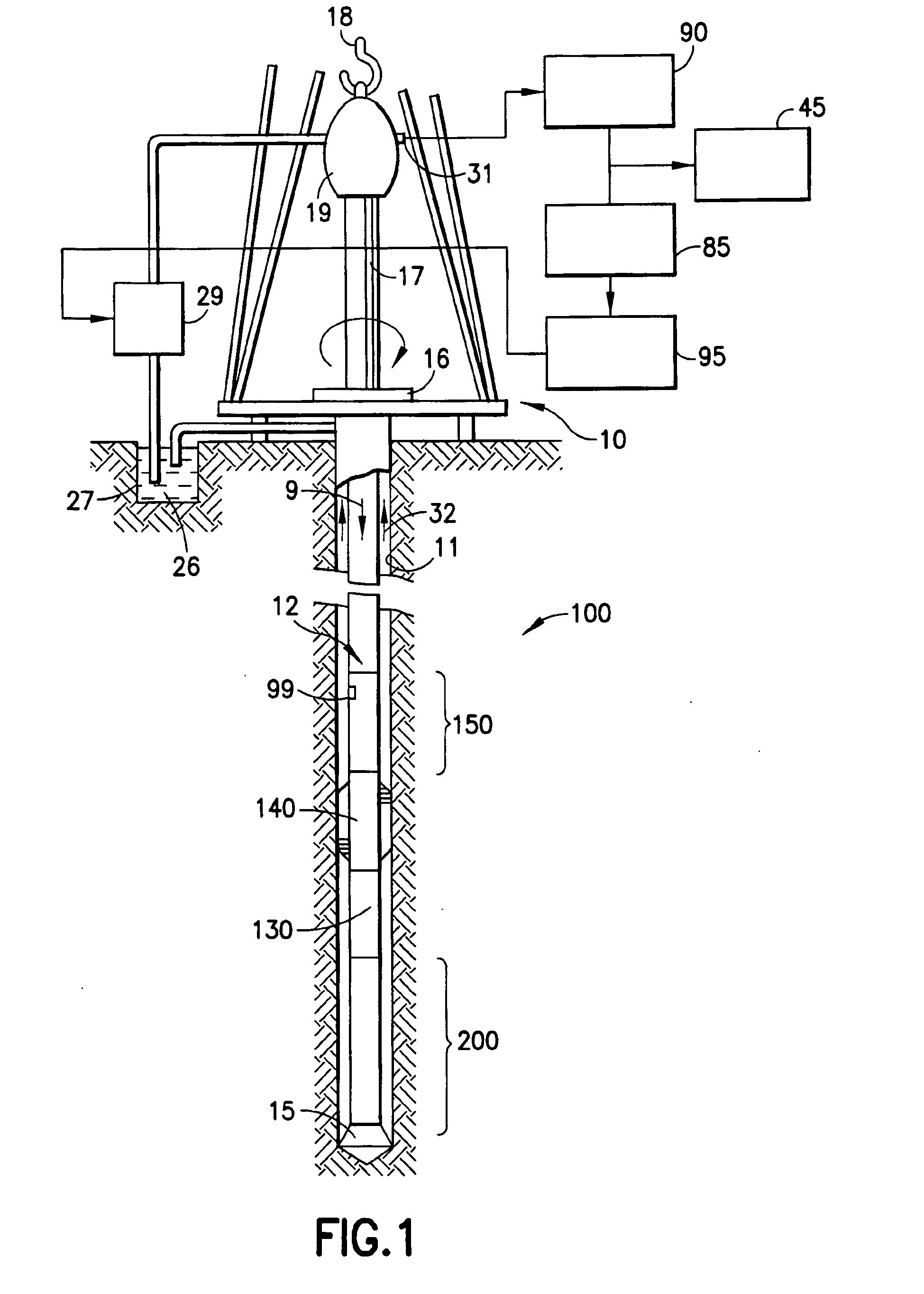
[0018]Referring to FIG. 1, there is illustrated a measuring-while-drilling apparatus which can be used in practicing embodiments of the invention. [As used herein, and unless otherwise specified, measurement-while-drilling (also called measuring-while-drilling or logging-while-drilling) is intended to include the taking of measurements in an earth borehole, with the drill bit and at least some of the drill string in the borehole, during drilling, pausing, and / or tripping.] A platform and derrick 10 are positioned over a borehole 11 that is formed in the earth by rotary drilling. A drill string 12 is suspended within the borehole and includes a drill bit 15 at its lower end. The drill string 12 and the drill bit 15 attached thereto are rotated by a rotating table 16 (energized by means not shown) which engages a kelly 17 at the upper end of the drill string. The drill string is suspended from a hook 18 attached to a traveling block (not shown). The kelly is connected to the hook thro...


PUM


Abstract

A method and apparatus for measuring a substance in formations surrounding an earth borehole being drilled with a drill bit at the end of a drill string, using drilling fluid that flows downward through the drill string, exits through the drill bit entrained with drilled earth formation cuttings, and returns toward the earth's surface in the annulus between the drill string and the borehole, the method including the following steps: waiting for any of the substance that is dissolved in the drilling fluid to be substantially in equilibrium with any of the substance in the earth formation cuttings; and then measuring, downhole, the substance dissolved in the drilling fluid.

Description

RELATED APPLICATION[0001]The subject matter of the present Application is related to subject matter in copending U.S. patent application Ser. No. 11 / 558,648, (File 60.1626 US NP) by A. B. Andrews, J. Tarvin, and K. Stephenson, filed of even date herewith, and assigned to the same assignee as the present Application.FIELD OF THE INVENTION[0002]The invention relates to the downhole measurement, during the drilling process, of substances in earth formations surrounding an earth borehole.BACKGROUND OF THE INVENTION[0003]Prior to the introduction of Logging While Drilling (LWD) tools and measurements, analysis of cuttings and mud-gas logging were the primary formation evaluation techniques used during drilling. With the advent of LWD, mud-gas logging became less essential, but recently has regained importance as operators have been able to extract valuable reservoir information that had not been obtainable by other relatively inexpensive methods.[0004]The present-day approach to mud-gas ...

Claims


Application Information

Patent Timeline
Patent Type & Authority Applications(United States)
IPC IPC(8): E21B47/00G01J3/44
CPCE21B49/005G01N21/65G01V8/02G01N2201/0697G01N21/658
Inventor STEPHENSON, KENNETH E.TARVIN, JEFFREY A.
Owner SCHLUMBERGER TECH CORP
Learn More