Mining utility transport vehicle

a transportation vehicle and mining technology, applied in the field of vehicles, can solve the problems of no external drive shaft, universal joint, shaft bearing, clutch type equipment, etc., and achieve the effects of low cost, low cost, and high stress

Inactive Publication Date: 2008-05-08
LISTERHILL TOTAL MAINTENANCE CENT
View PDF1 Cites 1 Cited by
  • Summary
  • Abstract
  • Description
  • Claims
  • Application Information

AI Technical Summary

Benefits of technology

[0007]Disclosed is a vehicle sized and configured to make it suitable for transporting mining equipment and personnel for extended distances and durations with little or no significant downtime. Design criteria focus on elimination or reduction of lubricated joints, exposed rotating equipment, and complicated control systems. In a particularly preferred embodiment, the vehicle has two main bodies, one a power and control section and the other a payload section, the two sections being connected by an articulating joint. The power and control section preferably has seating for an operator and a passenger. The payload section preferably has seating for multiple passengers, preferably at least four passengers, as well as capacity for at least 2000 pounds of equipment. The weight distribution of each section is such that the stress on the frame and articulating joint is minimized, thus providing improved life of the joint.
[0008]It is desired to provide the mining industry with a vehicle for the transportation of personnel and equipment that can operate continuously with reduced maintenance based on scheduled minor servicing. A vehicle that is capable of meeting these criteria provides a significantly lower cost of operation and reduced loss of operation, thereby improving mine output capability by having workers at the needed locations immediately. Since operation of the vehicle includes traversing pools of salt and silted water, the design includes methods for self-bailing floors and protection of power and drive systems from submersion or exposure. Those components that could be exposed are constructed from materials that are resistant or minimally compromised by rust and corrosion.
[0010]An additional feature of the invention is an articulated joint for connecting the power section and payload section together that allows each section to move rotationally about vertical and horizontal axes. Very high stresses occur in the area of the articulated joint due to the environmental conditions of the mine and rough terrain. Materials designed in the articulated joint preferably include hardened pins, an aluminum / bronze graphite impregnated bushing, high impact non-corrosive liner material, and a hardened backer plate for minimal wear of the rotational device. Furthermore, the stresses on each end of the joint are minimized through the balance of each connected car to improve life of the articulated joint. The joint is designed such that in case of failure, it can be removed and another unit bolted in place.

Problems solved by technology

No external drive shafts, universal joints, shaft bearings, transmission, or clutch type equipment exists for fouling and failure.
Very high stresses occur in the area of the articulated joint due to the environmental conditions of the mine and rough terrain.

Method used


Image

  • Mining utility transport vehicle
  • Mining utility transport vehicle
  • Mining utility transport vehicle

Examples


Embodiment Construction

[0024]The invention summarized above may be better understood by referring to the following description, which should be read in conjunction with the accompanying drawings in which like reference numbers are used for like parts. This description of an embodiment, set out below to enable one to practice an implementation of the invention, is not intended to limit the preferred embodiment, but to serve as a particular example thereof. Those skilled in the art should appreciate that they may readily use the conception and specific embodiments disclosed as a basis for modifying or designing other methods and systems for carrying out the same purposes of the present invention. Those skilled in the art should also realize that such equivalent assemblies do not depart from the spirit and scope of the invention in its broadest form.

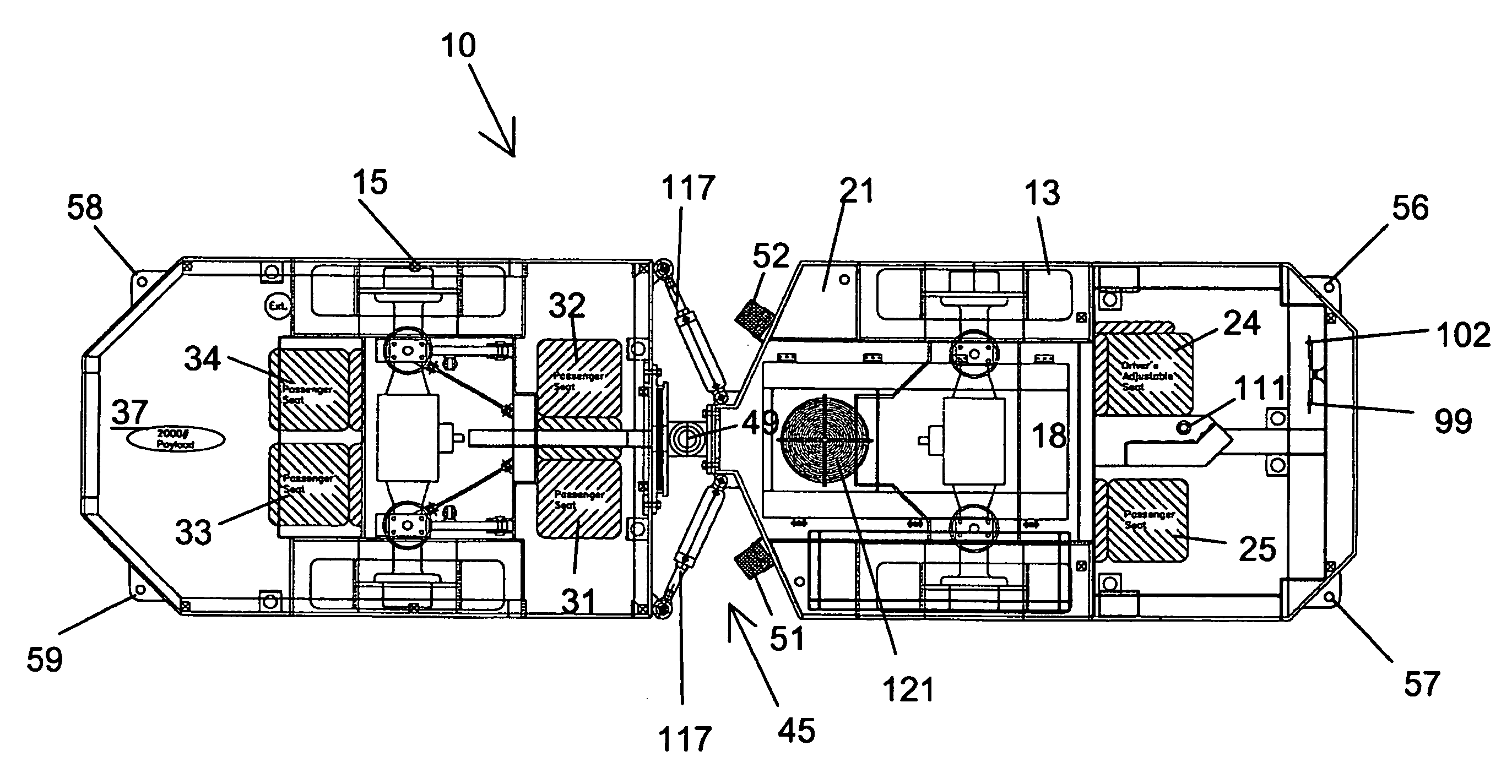
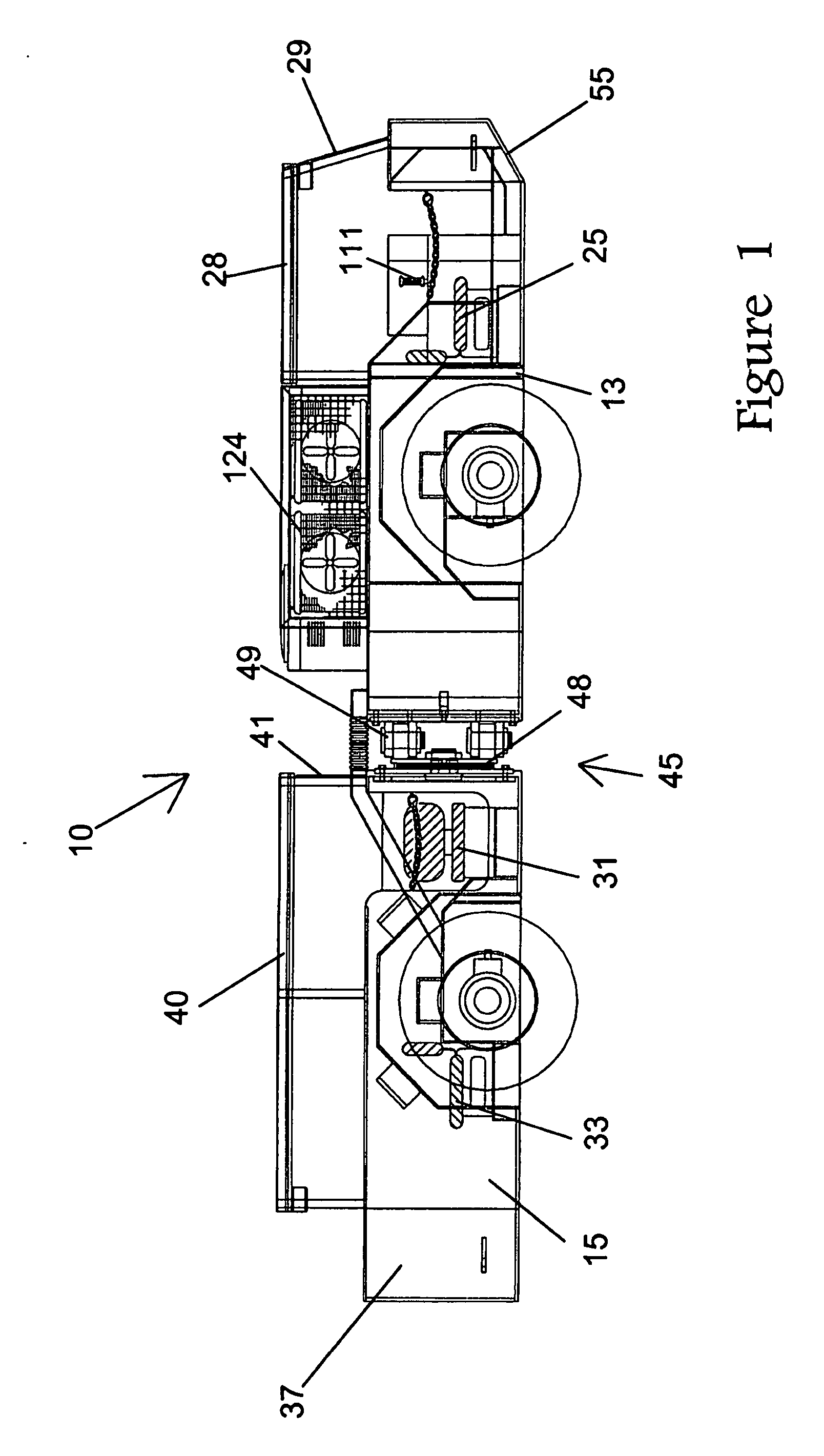
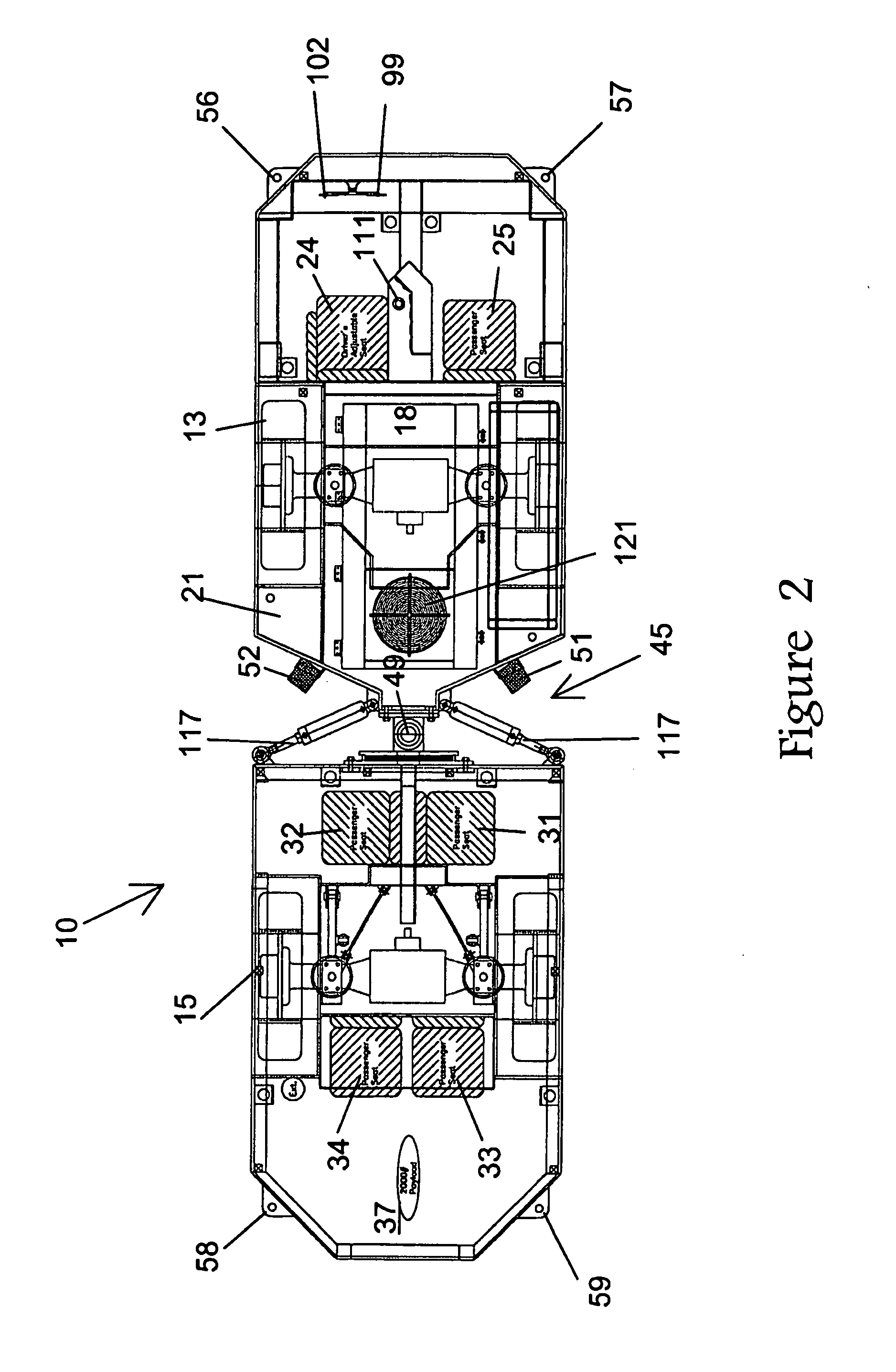
[0025]Referring now to the drawings, FIGS. 1-4 show a vehicle, indicated generally as 10, according to the present invention. The vehicle 10 comprises a power an...


PUM


Abstract

A mine transport vehicle is disclosed having two main bodies, one a power and control section and the other a payload section, the two sections being connected by an articulating joint. The power and control section has seating for an operator and a passenger. The payload section has seating for four passengers as well as capacity for at least approximately 2000 pounds of equipment. The weight distribution of each section is such that the stress on the frame and articulating joint is minimized thus providing improved life of the joint.

Description

CROSS REFERENCE TO RELATED APPLICATION[0001]This application is based upon and claims benefit of copending U.S. Provisional Patent Application Serial No. 60 / 794,740 entitled “Mining Utility Transport Vehicle”, filed with the U.S. Patent and Trademark Office on Apr. 25, 2006 by the inventors herein, the specification of which is incorporated herein by reference.BACKGROUND OF THE INVENTION[0002]1. Field of the Invention[0003]This invention generally relates to vehicles and, in particular, to a vehicle specifically designed for reliable transportation of personnel and equipment for the mining industry.[0004]2. Background of the Prior Art[0005]Operation of vehicles for the transportation of personnel and equipment in deep shaft mines poses problems unlike most other mining operations. The environment of operation includes rough and irregular terrain, poor visibility and clearances, typically rough treatment of equipment, long and often continuous hours of operation from shift to shift, ...

Claims


Application Information

Patent Timeline
IPC IPC(8): B60R16/00
CPCE21F13/004B62D53/021
Inventor FLOURNOY, DONALD B.PATTERSON, FLOYD T.STUMPE, MICHAEL J.BRYERTON, JOHN F.CANTRELL, HILARD R.ELLETT, TIMOTHY A.
Owner LISTERHILL TOTAL MAINTENANCE CENT
Why Eureka
Try Eureka