Plasma apparatus and plasma processing method

Inactive Publication Date: 2008-05-01
FUJIFILM CORP
View PDF8 Cites 49 Cited by
  • Summary
  • Abstract
  • Description
  • Claims
  • Application Information

AI Technical Summary

Benefits of technology

[0021] Due to the above-mentioned problem, despite its advantages in that it helps to provide low-temperature / low-pressure / high-density plasma, allows processing at low temperature with low damage, and provides a satisfactory film quality, the ICP system is rather difficult to apply to large area apparatuses intended for large substrates, and is mainly applied to small apparatuses.
[0022] The present invention has been made with a view toward solving the above-mentioned problems in the prior art. It is a first object of the present invention to provide a plasma apparatus for use in a plasma CVD apparatus or the like which makes it possible to perform processing on a large area substrate in a satisfactory manner and to attain a high productivity by utilizing the ICP system which advantageously helps to provide low-temperature / low-pressure / high-density plasma, allows processing at low temperature with low damage, and provides a satisfactory film quality.
[0039] Thus, even when processing is to be performed on a large area substrate, it is only necessary to elongate the linear electric field forming means and the dielectric window. Thus, according to the present invention, it is possible to perform processing on a large area substrate without involving a two-dimensional increase in the size of the electric field forming means, the dielectric window, and the gas introducing means; further, the design of the coil is facilitated, and there is no need to increase the thickness of the dielectric window. Further, it is possible to uniformly supply a sufficient amount of gas in correspondence with the entire processing region of the substrate by a gas introducing means of a simple construction, such as means obtained by forming a through-hole in a pipe. Thus, according to the present invention, even in the case of a large area substrate, it is possible to perform, in a satisfactory manner, a processing such as a formation of a thin film uniform over the entire surface thereof.

Problems solved by technology

Thus, in order to perform a large area processing, it is necessary to design an accordingly large coil capable of forming a uniform induction electric field, which means the design of the coil is very difficult.
Further, the apparatus is quite liable to be increased in size and complicated.

Method used


Image

  • Plasma apparatus and plasma processing method
  • Plasma apparatus and plasma processing method
  • Plasma apparatus and plasma processing method

Examples


Embodiment Construction

[0049] In the following, a plasma apparatus and a plasma processing method according to the present invention will be described in detail with reference to preferred embodiments shown in the accompanying drawings.

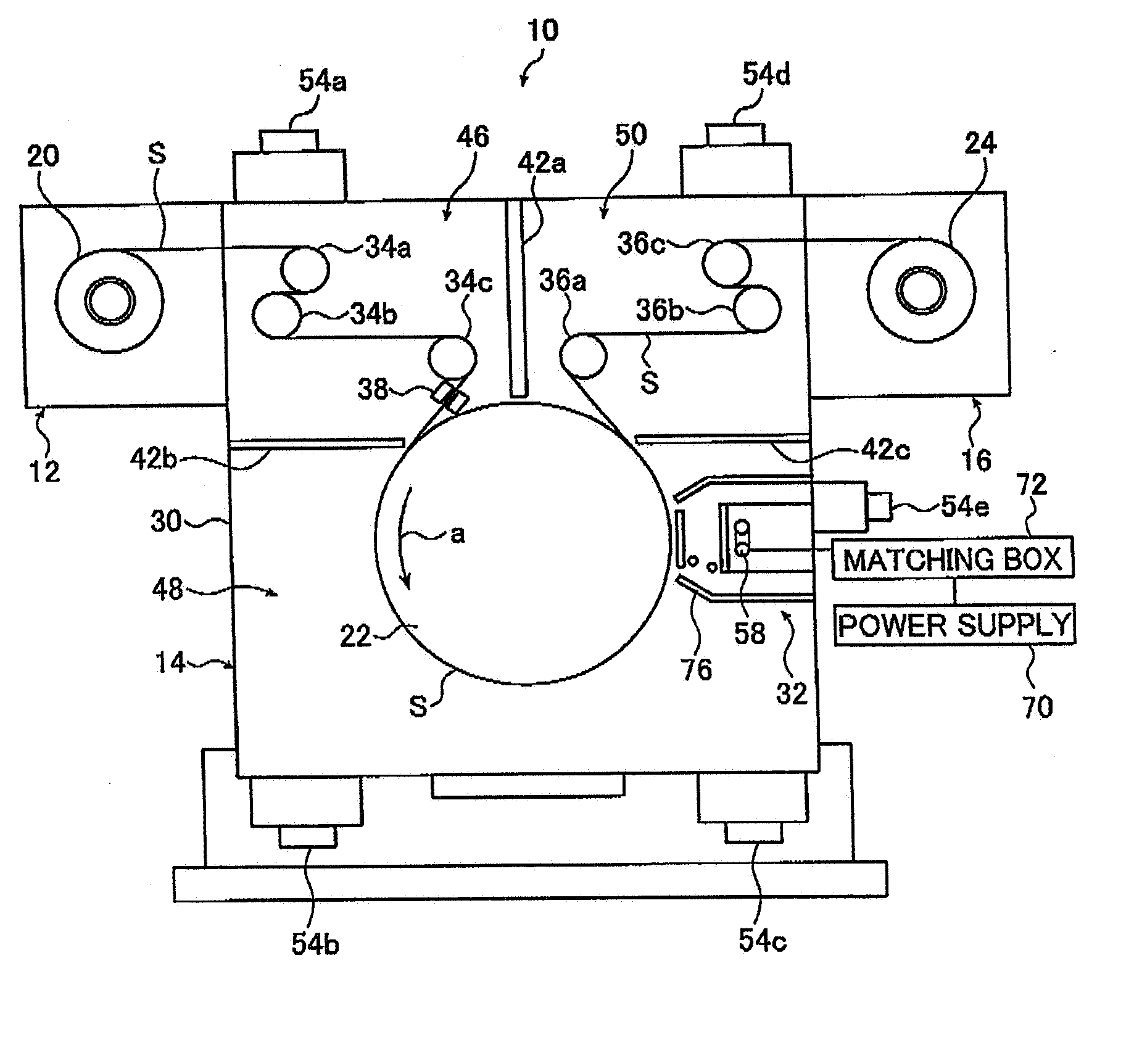
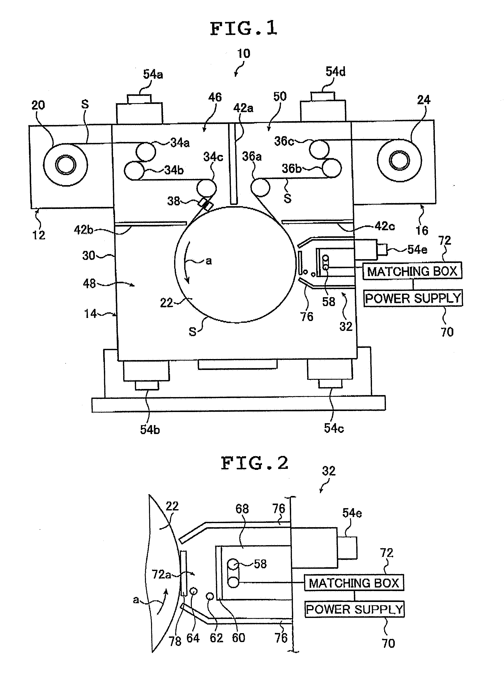
[0050]FIG. 1 is a conceptual diagram showing an embodiment in which the plasma processing apparatus of the present invention for executing the plasma processing method of the present invention is applied to a plasma CVD apparatus.

[0051]FIG. 1 shows a plasma CVD apparatus 10 which forms a thin film on the surface of an elongated substrate S by plasma CVD of the inductively coupled plasma (ICP) system and which basically includes a feeding portion 12 for feeding the substrate 5, a film forming portion 14 for forming a thin film on the surface of the substrate S by plasma CVD based on the ICP plasma system, and a take-up portion 16 for winding into a roll the substrate S on whose surface a thin film has been formed.

[0052] Here, the film forming portion 14 performs a film fo...


PUM

PropertyMeasurementUnit
Dielectric polarization enthalpyaaaaaaaaaa
Widthaaaaaaaaaa
Electric fieldaaaaaaaaaa

Abstract

The plasma apparatus includes a conveying unit for conveying a substrate in a conveying direction while being situated at a processing position, an elongated electric field forming unit for forming an induction electric field by a coil, opposed to the processing position, a power supply for supplying high frequency power to the coil, an elongated gas introducing unit and a separating unit for separating a region where the forming unit is arranged and a region where the introducing unit is arranged from each other in an airtight fashion, having an elongated dielectric window arranged between the processing position and the forming unit. The forming unit, the introducing unit and the dielectric window are arranged in such a way that there longitudinal directions are matched with a width direction of the substrate being conveyed, and orthogonal to the conveying direction.

Description

[0001] The entire contents of documents cited in this specification are incorporated herein by reference. BACKGROUND OF THE INVENTION [0002] The present invention relates to a technical field of plasma processing such as a film formation by plasma CVD, in particular, to a plasma apparatus and a plasma processing method making it possible to perform a continuous processing on an elongated substrate by an ICP system allowing a high quality and high speed processing. [0003] As plasma forming methods for a plasma CVD apparatus, there are known a capacitively coupled plasma (CCP) system and an inductively coupled plasma (ICP) system. [0004] In the CCP plasma system (hereinafter referred to as CCP system), a high frequency voltage is applied to two electrodes opposed to each other, thereby forming plasma between the electrodes. [0005] The CCP system is advantageous, for example, in that it is of a simple construction and that it can easily meet a demand for an increase in size through an ...

Claims


Application Information

Patent Timeline
IPC IPC(8): C23C16/50H05H1/24
CPCC23C16/45578C23C16/507H01J37/3277H01J37/321H01J37/3244C23C16/545
Inventor FUJINAWA, JUNKADOTA, NORIHIRO
Owner FUJIFILM CORP
Why Eureka
Try Eureka