
Liquid crystal device and electronic equipment

a liquid crystal and electronic equipment technology, applied in non-linear optics, instruments, optics, etc., can solve the problems of disadvantageous lowering of display contrast and insufficient brightness, and achieve the effect of high display quality and high reliability

Inactive Publication Date: 2008-05-01
JAPAN DISPLAY WEST
View PDF6 Cites 38 Cited by
  • Summary
  • Abstract
  • Description
  • Claims
  • Application Information

AI Technical Summary

Benefits of technology

"The invention provides a liquid crystal device and electronic equipment with a desired coefficient of transmission in both the transmissive and reflective display areas. This is achieved by configuring the distance between the electrodes in the transmissive display area to be smaller than in the reflective display area. The optically anisotropic property of the liquid crystal material is proportional to the square of the electric field strength, so the phase differences in the retardations in the transmissive and reflective display areas may be equalized without using a multi-gap structure. The electrode width in the transmissive display area is smaller than in the reflective display area to restrain the numerical aperture in the transmissive display area. The invention also includes a liquid crystal device with a first electrode and second electrode arranged in the transmissive display area and the reflective display area, respectively, to increase the electric field generated between the electrodes and achieve a high optically anisotropic property in the transmissive display area."

Problems solved by technology

However, when white display (for example, the phase difference of λ / 4) is achieved in the reflective area, the phase difference in the transmissive area is λ / 4, and hence the brightness is not sufficient.
Therefore, the phase differences of the refractive index (retardation) do not match between the transmissive display area and the reflective display area, and hence the contrast of display is disadvantageously lowered.

Method used


Image

  • Liquid crystal device and electronic equipment
  • Liquid crystal device and electronic equipment
  • Liquid crystal device and electronic equipment

Examples


second embodiment

[0084]Referring now to FIG. 5 and FIG. 6, a second embodiment of the liquid crystal device according to an aspect of the invention.

[0085]FIG. 5 is a plan view showing a configuration of a given sub-pixel area according to a liquid crystal device 200 in the second embodiment, and FIG. 6 is a view partly in cross section taken along the line A-A′ and B-B′ in FIG. 5.

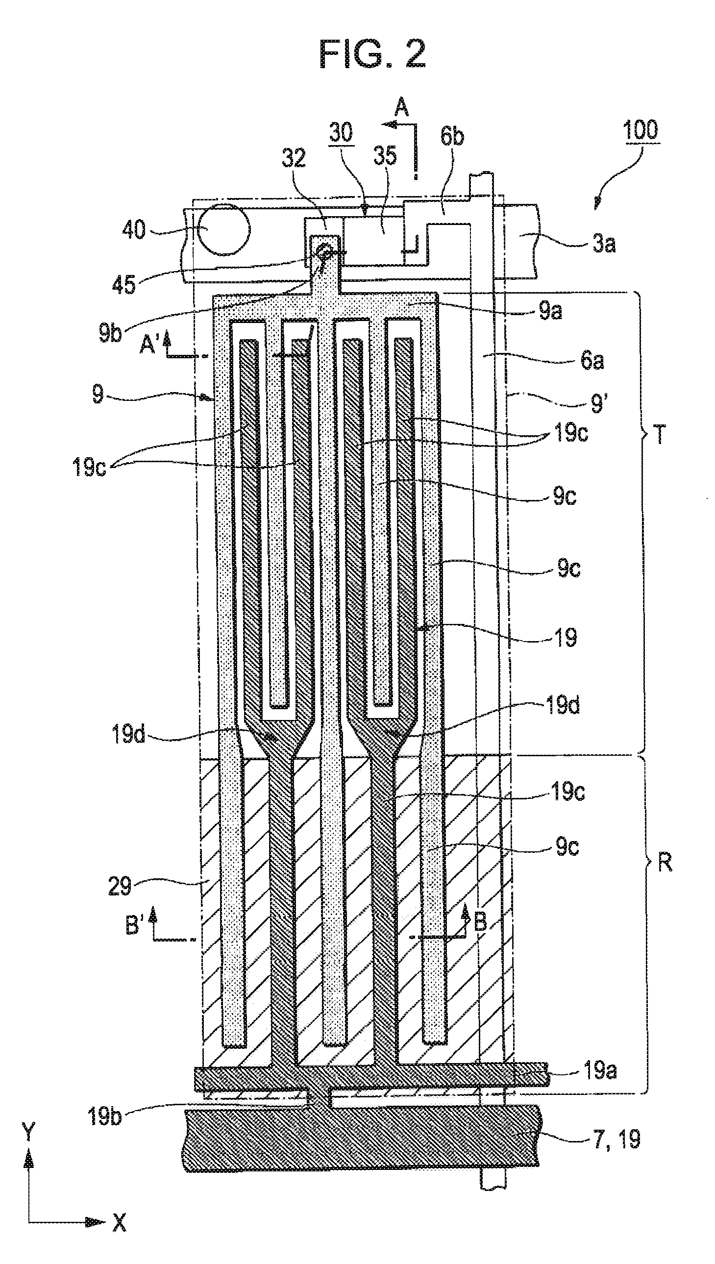
[0086]The basic configuration of the liquid crystal device 200 in the second embodiment is similar to the first embodiment shown above, and is different from the first embodiment in the shapes of the pixel electrode and the common electrode. FIG. 5 is a drawing corresponding to FIG. 2 in the first embodiment, and FIG. 6 is a drawing corresponding to FIG. 3 in the first embodiment. Therefore, in the respective drawings which are referenced in the second embodiment, the same parts as the liquid crystal device 100 in the first embodiment shown from FIG. 1 to FIG. 3 are represented by the same reference numerals, and descriptio...


PUM

PropertyMeasurementUnit
response timeaaaaaaaaaa
electric fieldaaaaaaaaaa
optical anisotropyaaaaaaaaaa

Abstract

A liquid crystal device including a liquid crystal layer having liquid crystal which demonstrates an optically isotropic property when no electric field is applied and demonstrates an optically anisotropic property which is proportional to the square of the electric field strength when electric field is applied, and a pair of substrates which sandwich the liquid crystal layer, including sub-pixel areas each including a reflective display area for reflective display and a transmissive display area for transmissive display; and first and second electrodes provided in both of the reflective display area and the transmissive display area, wherein the liquid crystal layer is driven by an electric field generated between the first electrode and the second electrode, and wherein the distance between the first electrode and the second electrode in the transmissive display area is smaller than the distance between the first electrode and the second electrode in the reflective display area.

Description

BACKGROUND[0001]1. Technical Field[0002]The present invention relates to a liquid crystal device and electronic equipment.[0003]2. Related Art[0004]In recent years, a display system with electronic polarization using an electro-optic effect is proposed. The electro-optic effect is a phenomenon in which the refractive index of a substance is changed by an external electric field. For example, Kerr effect is known as the electro-optic effect. The Kerr effect indicates a phenomenon in which when an electric field is applied to an isotropic polar substance, the birefringence which is proportional to the square of the electric field strength with the direction of the electric field as an optical axis is excited. As a liquid crystal material which develops such Kerr effect, a blue phase is known. The blue phase, being an optically isotropic liquid crystal phase which appears in a specific temperature range between a chiral nematic phase and an isotropic phase, is referred to as the blue p...

Claims


Application Information

Patent Timeline
Patent Type & Authority Applications(United States)
IPC IPC(8): G02F1/1343
CPCG02F1/133555G02F1/134363G02F2001/134372G02F1/13731G02F2001/133541G02F1/13718G02F1/133541G02F1/134372G02F1/1335
Inventor HARUYAMA, AKIHIDE
Owner JAPAN DISPLAY WEST
Learn More