
Phase locked loop without a charge pump and integrated circuit having the same

a technology of charge pump and integrated circuit, which is applied in the direction of phase difference detection angle demodulation, automatic control of pulses, electrical apparatus, etc., can solve the problem of complex charge pump in the conventional phase loop, and achieve the effect of reducing power consumption

Inactive Publication Date: 2008-05-01
SAMSUNG ELECTRONICS CO LTD
View PDF4 Cites 8 Cited by
  • Summary
  • Abstract
  • Description
  • Claims
  • Application Information

AI Technical Summary

Benefits of technology

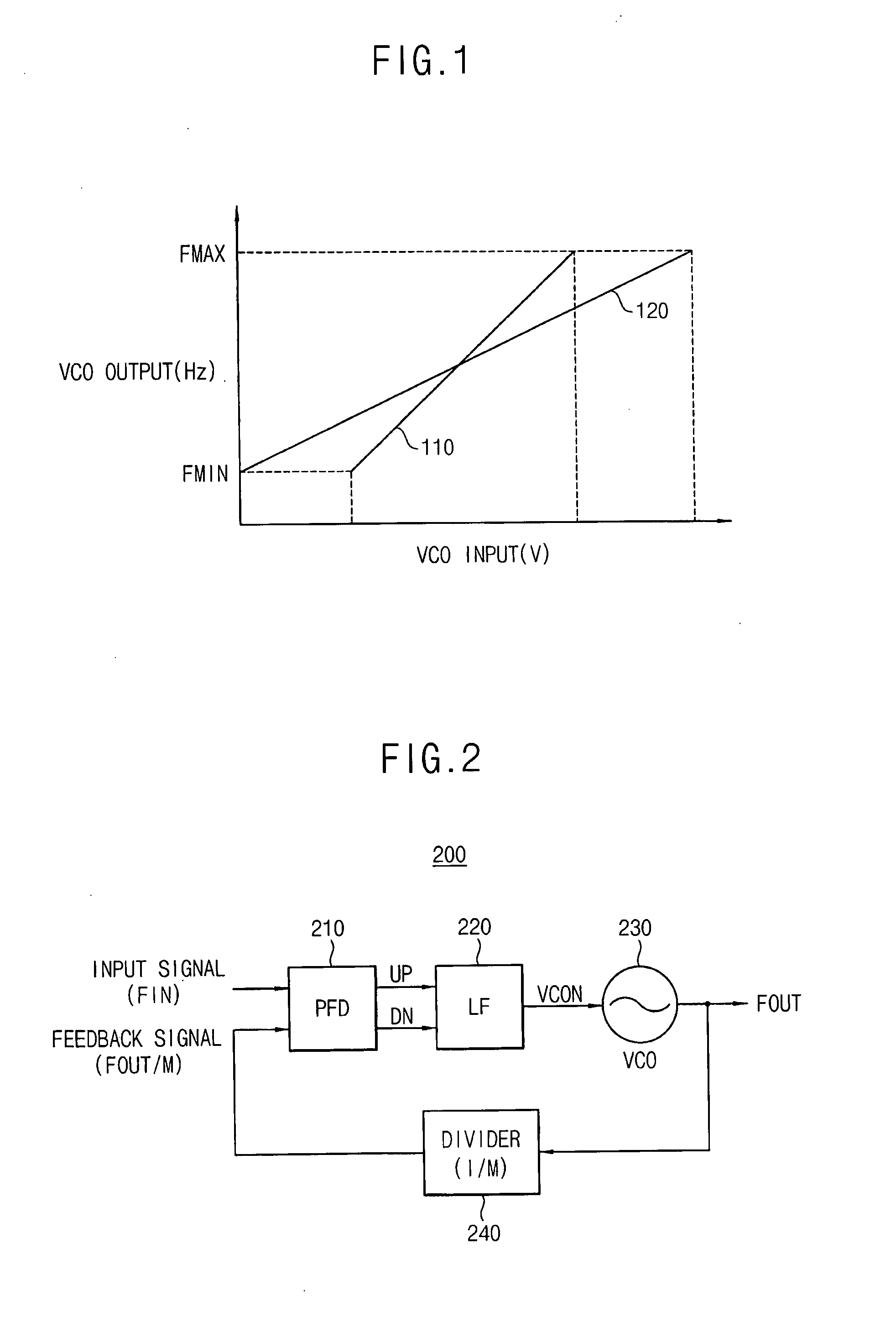
[0011]In accordance with the present invention a phase locked loop can be provided that is capable of operating at a relatively low voltage and operating based on a control voltage with a wide input range.
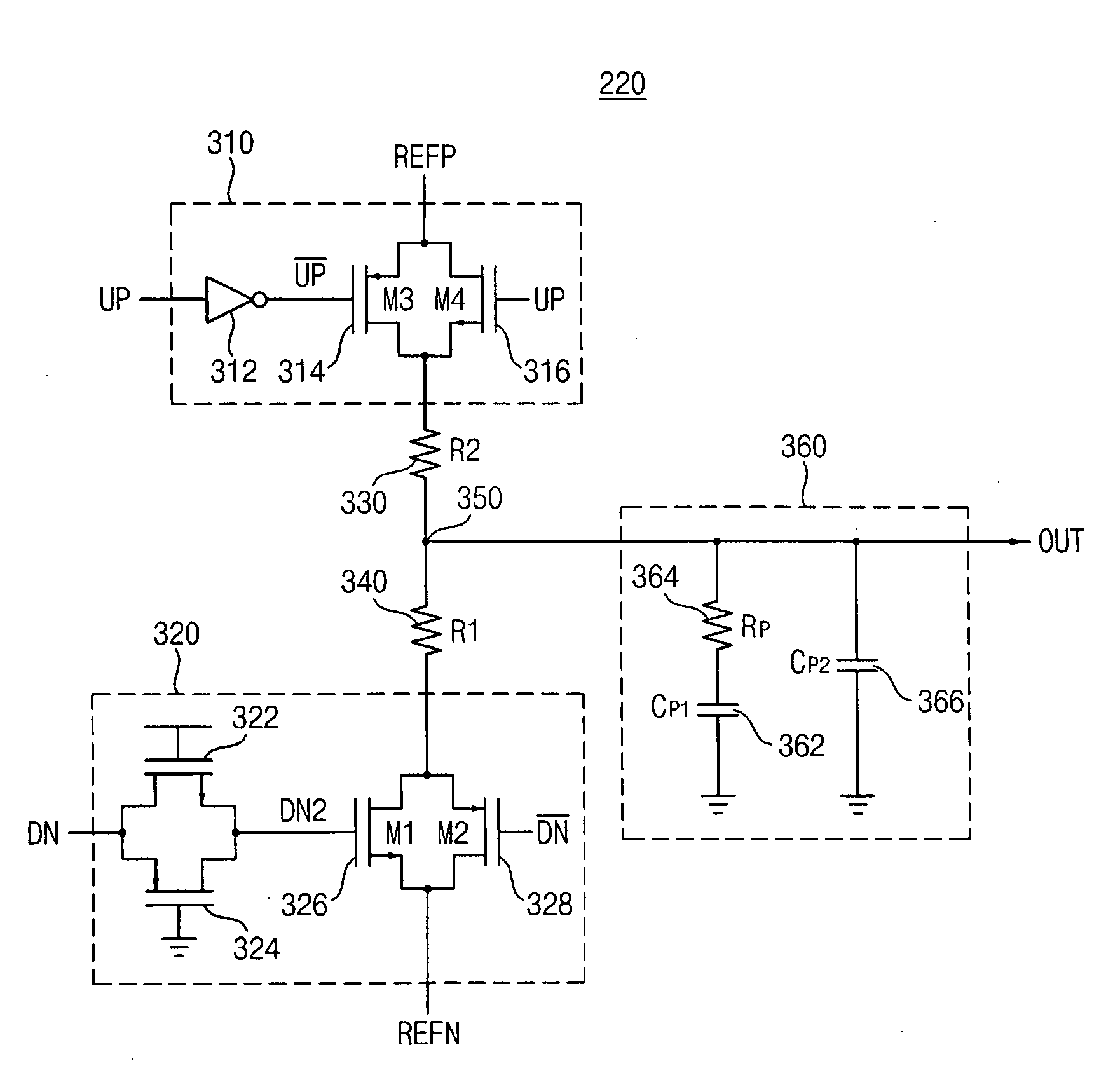
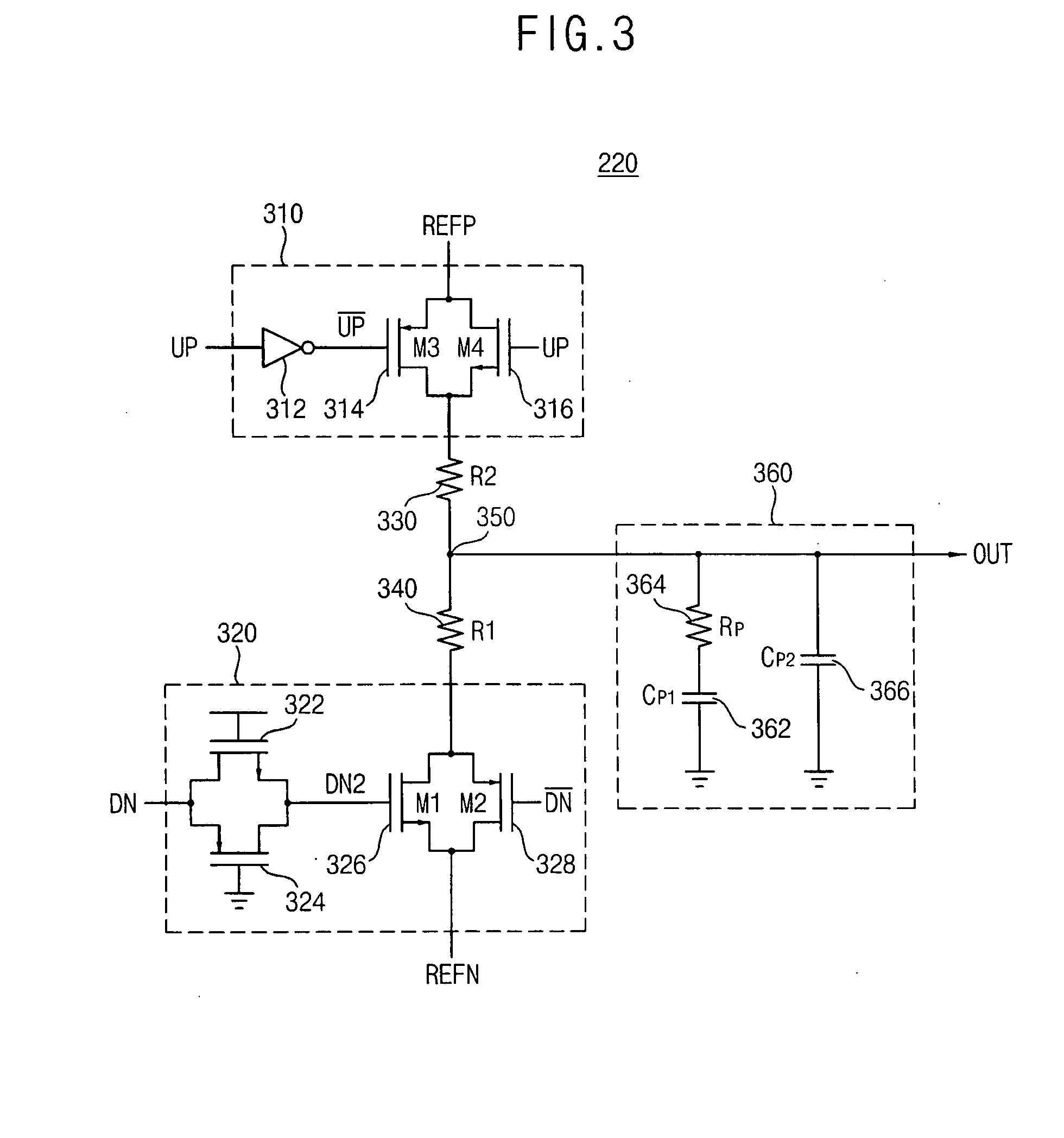
[0017]The loop filter can be configured to receive the first and the second reference voltages to cause a current flowing through a path formed by the pull-up resistor and the pull-down resistor to decrease power consumption when the first and the second control signals are inputted to the loop filter.
[0027]The loop filter can be configured to receive the first and the second reference voltages to cause a current through a path formed by the pull-up resistor and the pull-down resistor to decrease power consumption when the first and the second control signals are inputted to the loop filter.

Problems solved by technology

However, the charge pump in the conventional phase loop is complex, and the charge pump is required to be performed by a low voltage in a submicron process.

Method used


Image

  • Phase locked loop without a charge pump and integrated circuit having the same
  • Phase locked loop without a charge pump and integrated circuit having the same
  • Phase locked loop without a charge pump and integrated circuit having the same

Examples


Embodiment Construction

[0045]Embodiments in accordance with the present invention now will be described more fully with reference to the accompanying drawings. The invention can, however, be embodied in many different forms and should not be construed as limited to the embodiments set forth herein. Like reference numerals refer to like elements throughout this application.

[0046]It will be understood that, although the terms first, second, etc. may be used herein to describe various elements, these elements should not be limited by these terms. These terms are used to distinguish one element from another. For example, a first element could be termed a second element, and, similarly, a second element could be termed a first element, without departing from the scope of the present invention. As used herein, the term “and / or” includes any and all combinations of one or more of the associated listed items.

[0047]It will be understood that when an element is referred to as being “connected” or “coupled” to anoth...


PUM


Abstract

A phase locked loop includes a phase-frequency detector and a loop filter. The phase-frequency detector compares phases of an input signal and a feedback signal to generate first and second control signals. The loop filter includes a pull-up resistor, a pull-down resistor and a capacitance unit. The loop filter receives a first reference voltage to charge the capacitance unit through a path formed by the pull-up resistor to the capacitance unit, receives a second reference voltage to discharge the capacitance unit through a path formed by the pull-down resistor to the capacitance unit and outputs a control voltage generated based on a charge amount of the charged capacitance unit. Therefore, the phase locked loop can operate at a relatively low voltage and can operate based on a control voltage with a wide input range.

Description

CROSS-REFERENCE TO RELATED APPLICATIONS[0001]This application claims priority under 35 USC §119 to Korean Patent Application No. 10-2006-0104830 filed on Oct. 27, 2006 in the Korean Intellectual. Property Office (KIPO), the disclosure of which is incorporated herein in its entirety by reference.BACKGROUND OF THE INVENTION[0002]1. Field of the Invention[0003]The present invention relates to a phase locked loop (PLL), and more particularly to a PLL without a charge pump and an integrated circuit having the PLL.[0004]2. Description of the Related Art[0005]Various electronic devices include a PLL for stabilizing a generated signal having a desired frequency.[0006]Generally, a PLL can include a phase-frequency detector, a charge pump, a loop filter, a voltage-controlled oscillator (VCO) and a divider. The PLL detects a phase / frequency difference between an input signal (FIN) and a divided signal (FOUT / M) and controls a phase / frequency of an output signal (FOUT) based on a result of the d...

Claims


Application Information

Patent Timeline
IPC IPC(8): H03L7/06
CPCH03L7/0896H03L7/183H03L7/093
Inventor PARK, JAE-JIN
Owner SAMSUNG ELECTRONICS CO LTD
Learn More