
Spindle device

a technology of a pin and a rotating shaft, which is applied in the direction of machine/engine, rigid support of the bearing unit, manufacturing tools, etc., can solve the problems of increasing the consumption of fluid, inducing the worst damage to the bearing, and the retainer is unstably rotated, so as to prevent damage to the bearing caused by abrasion of the retainer. , the effect of rotating stably

Inactive Publication Date: 2008-04-24
OKUMA CORP
View PDF6 Cites 8 Cited by
  • Summary
  • Abstract
  • Description
  • Claims
  • Application Information

AI Technical Summary

Benefits of technology

[0008]An object of the present invention is to provide a spindle device, in which a retainer can be stabilized with a minimum quantity of fluid to be supplied, and further, a flow rate and direction of fluid to be supplied to a retainer can be varied based on a rotational speed of a spindle, an attitude of the spindle and a value from a sensor fixed to the spindle.
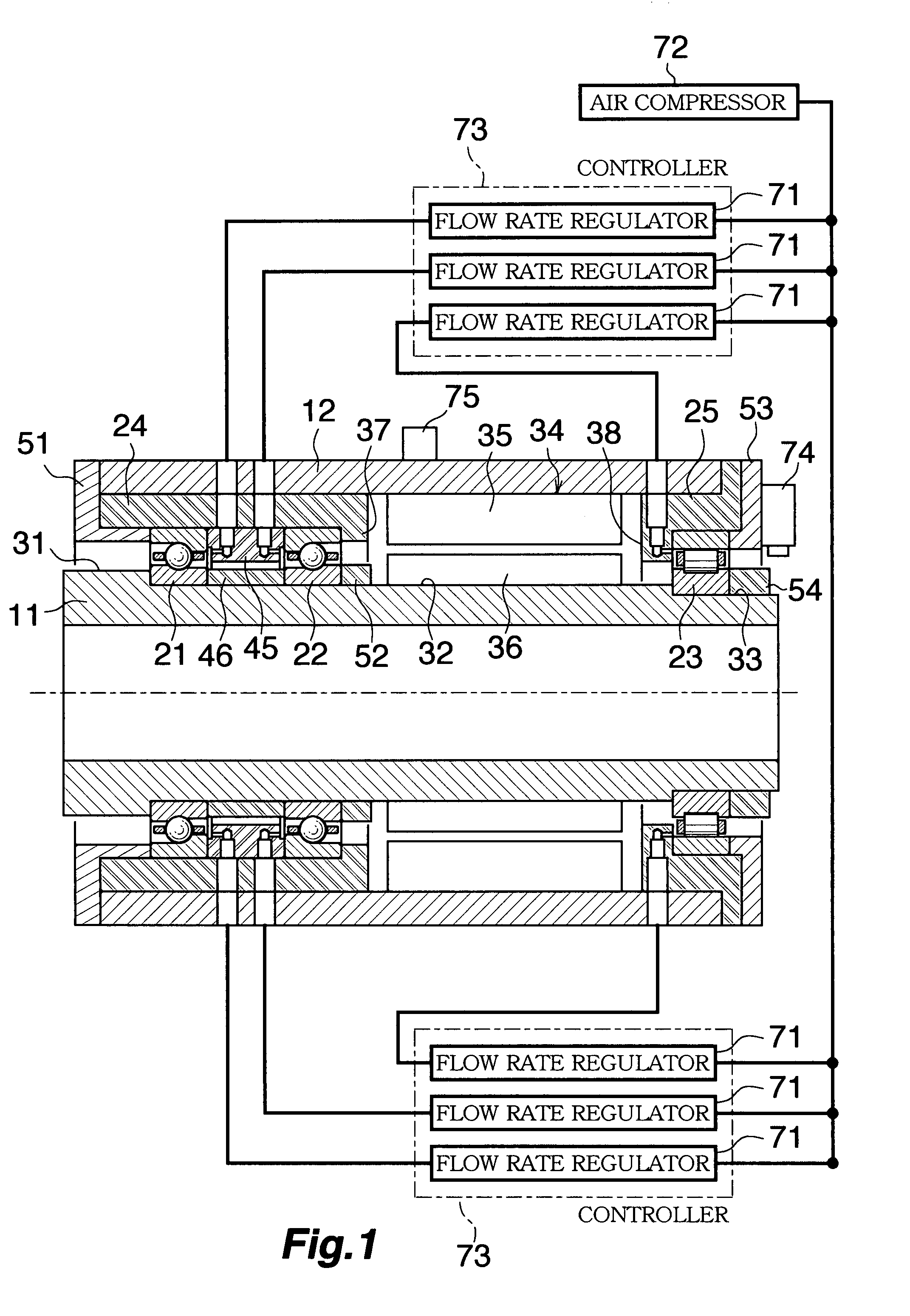
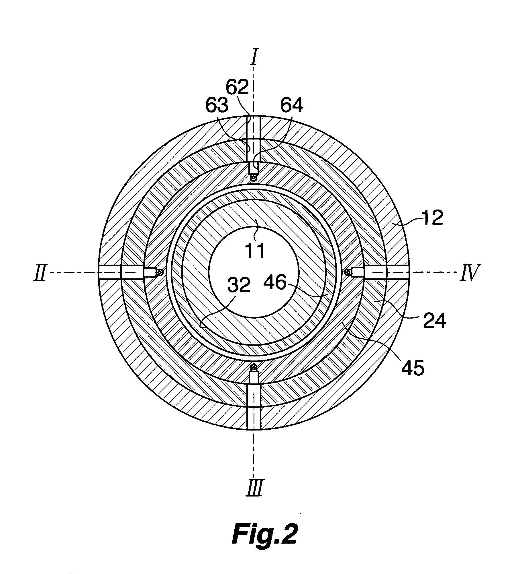
[0010]In the spindle device according to the present invention, even in the case where, for example, a retainer is rotated off balance, force can be exerted in a direction in which an imbalance is cancelled by regulating the flow rate of fluid through the three or more holes capable of independently supplying the fluid. As a consequence, the imbalance in the retainer can be reduced with a low flow rate of fluid.
[0017]According to the present invention, the flow rates and positions of the plurality of fluid supplying holes can be independently set, so that the retainer can be stably rotated in spite of the variation of the rotational speed or the attitude of the spindle. In addition, the flow rate and position of the fluid can be regulated in such a manner as to optimize the value from the sensor attached to the spindle device. Thus, it is possible to produce an effect in finishing requiring for a spindle rotational accuracy, and further, to produce an effect in preventing damage on the bearing caused by abrasion of the retainer.

Problems solved by technology

When the spindle is rotated in the state in which the above-described conditions cannot be properly kept, the retainer is unstably rotated.
As a result, an abnormal noise or vibration occurs, and therefore, a surface to be machined undergoes an adverse affect, thereby inducing damage on the bearing at the worst.
In the conventional spindle device, the fluid need be supplied all the time in order to keep a constant clearance between the inner circumferential surface of the outer race of the bearing and the outer peripheral surface of the retainer, thereby increasing the consumption of the fluid.
When the fluid to be supplied is the lubricant, the oil film can keep the constant clearance, but heat may be abnormally generated due to an excessive quantity of lubricant in the bearing.
In the case of a low circularity of the outer diameter of the retainer or non-uniform deformation caused by the rotation, it may be difficult to constantly keep the clearance between the inner circumferential surface of the outer race of the bearing and the outer peripheral surface of the retainer over the entire circumference.
Even if the lubricant can constantly keep an oil film quantity in the clearance, a frictional force locally occurs in the retainer, thereby inducing the fear of occurrence of vibrations.

Method used


Image

  • Spindle device
  • Spindle device
  • Spindle device

Examples


Embodiment Construction

[0024]A detailed description will be given below of a preferred embodiment according to the present invention in reference to the attached drawings.

[0025]In the description below, a left side in reference to FIG. 1 is referred to as the left, and further, a side opposite to the left side is referred to as a right. In addition, the left is a front side while the right is a rear side.

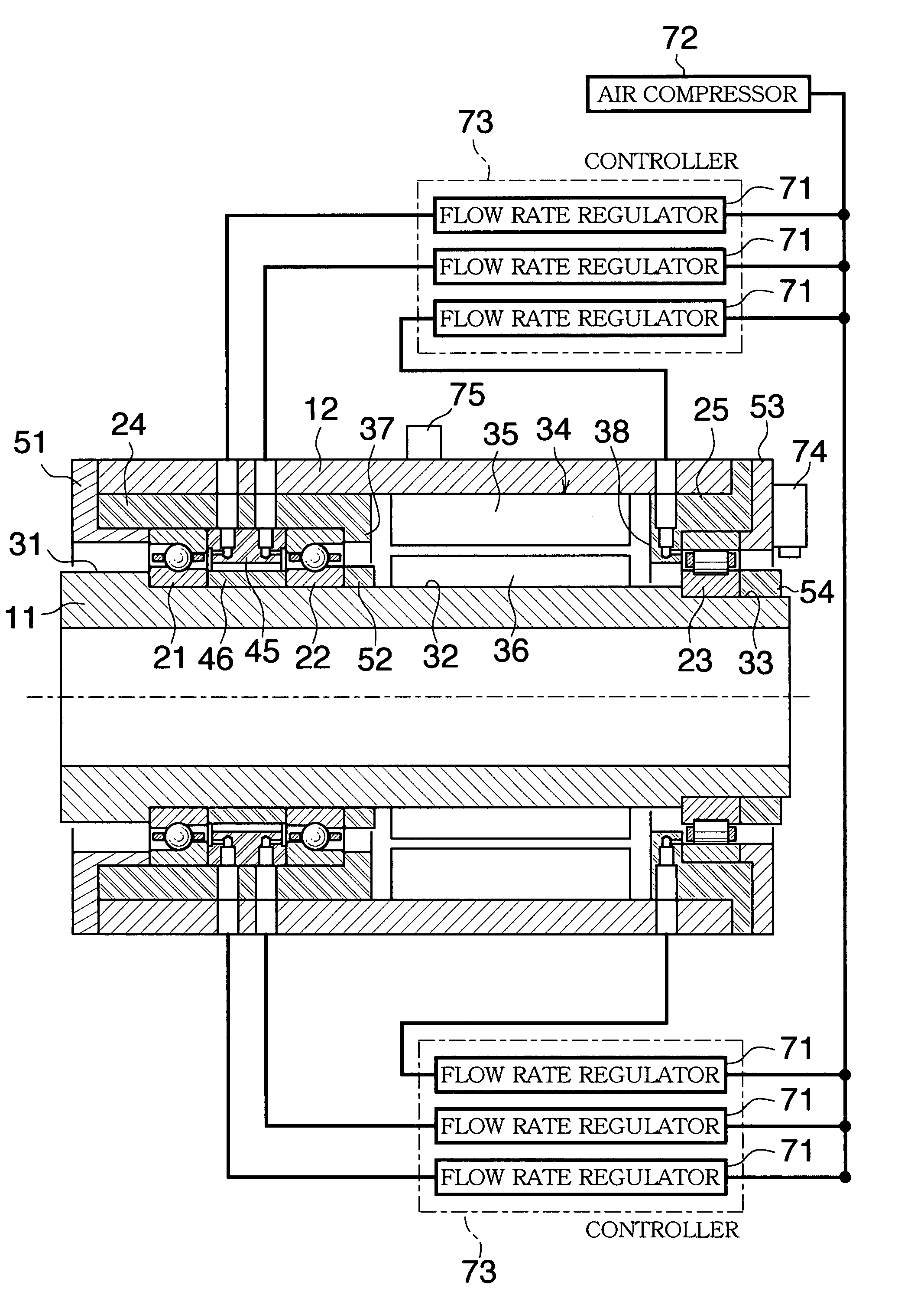
[0026]A spindle device is provided with a hollow spindle 11 having an axis in a horizontal direction, a horizontally cylindrical sleeve 12 fitted around the spindle 11, a first bearing 21 and a second bearing 22 which support the spindle 11 on the left side thereof with an axial interval, a third bearing 23 which supports the spindle 11 on the right side thereof, a left housing 24 which surrounds the first bearing 21 and the second bearing 22 and is fixed to an inner surface of the sleeve 12, and a right housing 25 which surrounds the third bearing 23 and is fixed to the inner surface of the sleeve 12.

[00...


PUM

PropertyMeasurementUnit
inclination angleaaaaaaaaaa
rotational speedaaaaaaaaaa
inclination angleaaaaaaaaaa

Abstract

An object of the present invention is to provide a spindle device for stabilizing a retainer with a minimum quantity of air to be supplied to the bearing. A spindle device includes: supplying unit which supplies air from three or more points spaced in a circumferential direction between outer races and inner races of bearings supporting a spindle; and control unit which controls a supply quantity of air supplied by the supplying unit in such a manner as to independently vary the supply quantity at each of the supplying points.

Description

BACKGROUND OF THE INVENTION[0001]1. Field of the Invention[0002]The present invention relates to a spindle device in a machining tool such as a machining center and, more particularly, to a spindle device which stably rotates a retainer for retaining a rolling element in a rolling-element bearing for supporting a spindle.[0003]2. Description of the Related Art[0004]A spindle in a machining tool is rotatably supported by a plurality of rolling-element bearings. The rolling-element bearing includes an inner race, an outer race, a rolling element and a retainer. The inner race is press-fitted to the spindle, to be rotated together with the spindle. In the meantime, the outer race is incorporated in a housing, and further, is securely pressed by a presser cap in an axial direction. The plurality of rolling-elements are movably incorporated between the inner race and the outer race, to be retained by the retainer in such a manner as to be held at equal intervals. The retainer is guided o...

Claims


Application Information

Patent Timeline
Patent Type & Authority Applications(United States)
IPC IPC(8): F01M9/12F16C35/08
CPCB23Q1/70B23Q11/0883B23Q17/12F16C35/12F16C33/6662F16C33/6674F16C19/54F16C2322/39
Inventor YANOHARA, NAOMITSUANDO, TOMOHARUNORIHISA, TAKASHI
Owner OKUMA CORP
Learn More