
Spark plug with stream shaper to shape tumble vortex into desired stream in combustion chamber

Inactive Publication Date: 2008-04-24
DENSO CORP +1
View PDF8 Cites 15 Cited by
  • Summary
  • Abstract
  • Description
  • Claims
  • Application Information

AI Technical Summary

Benefits of technology

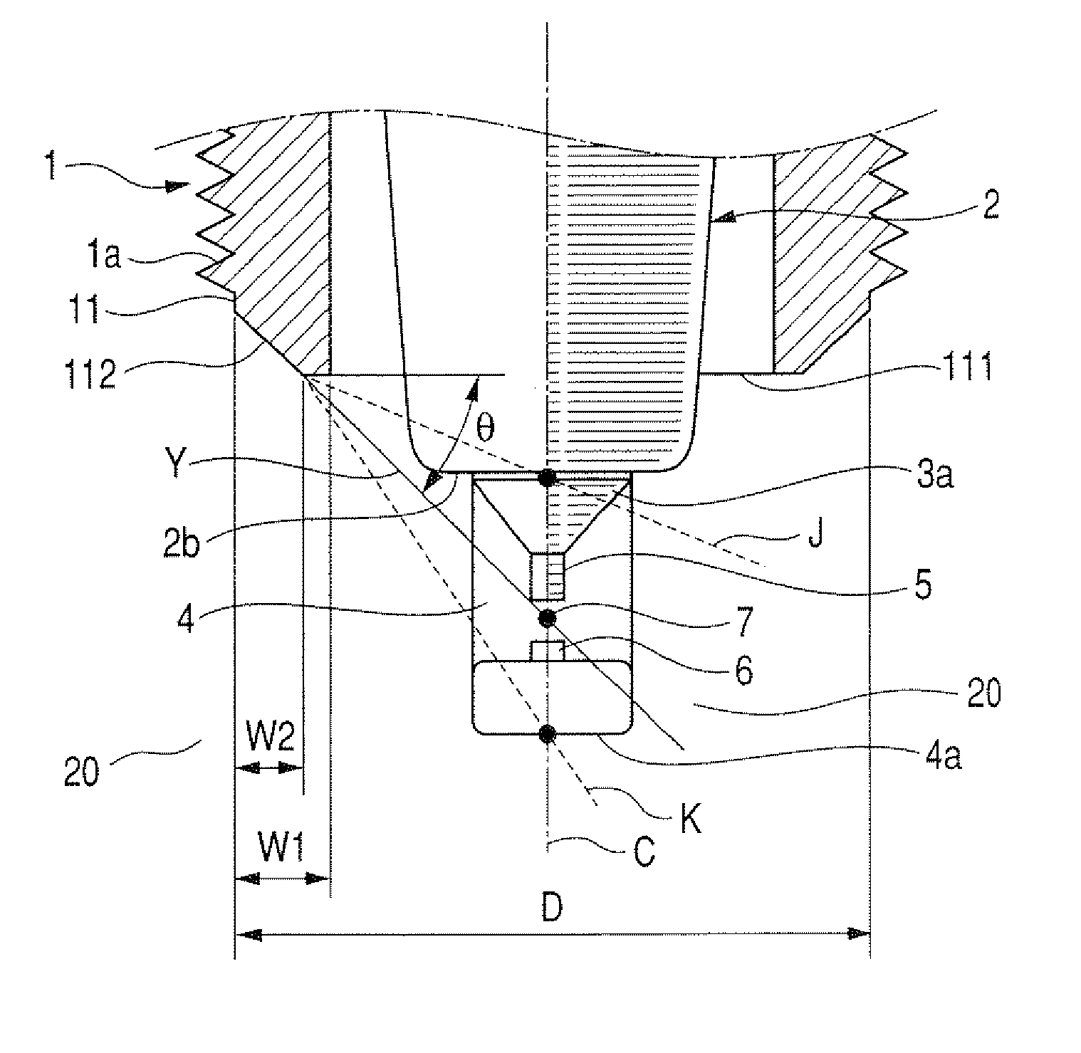
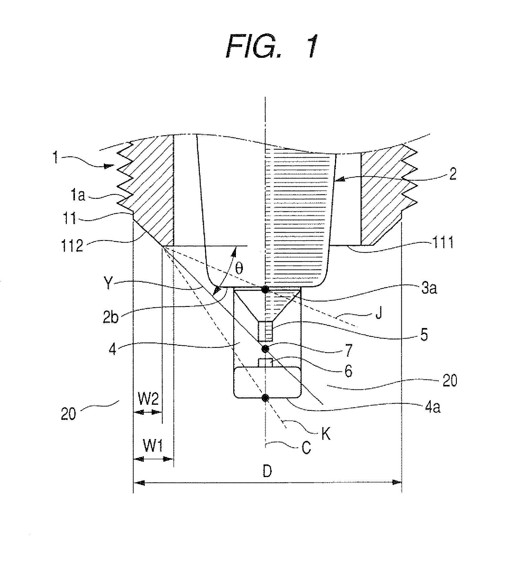
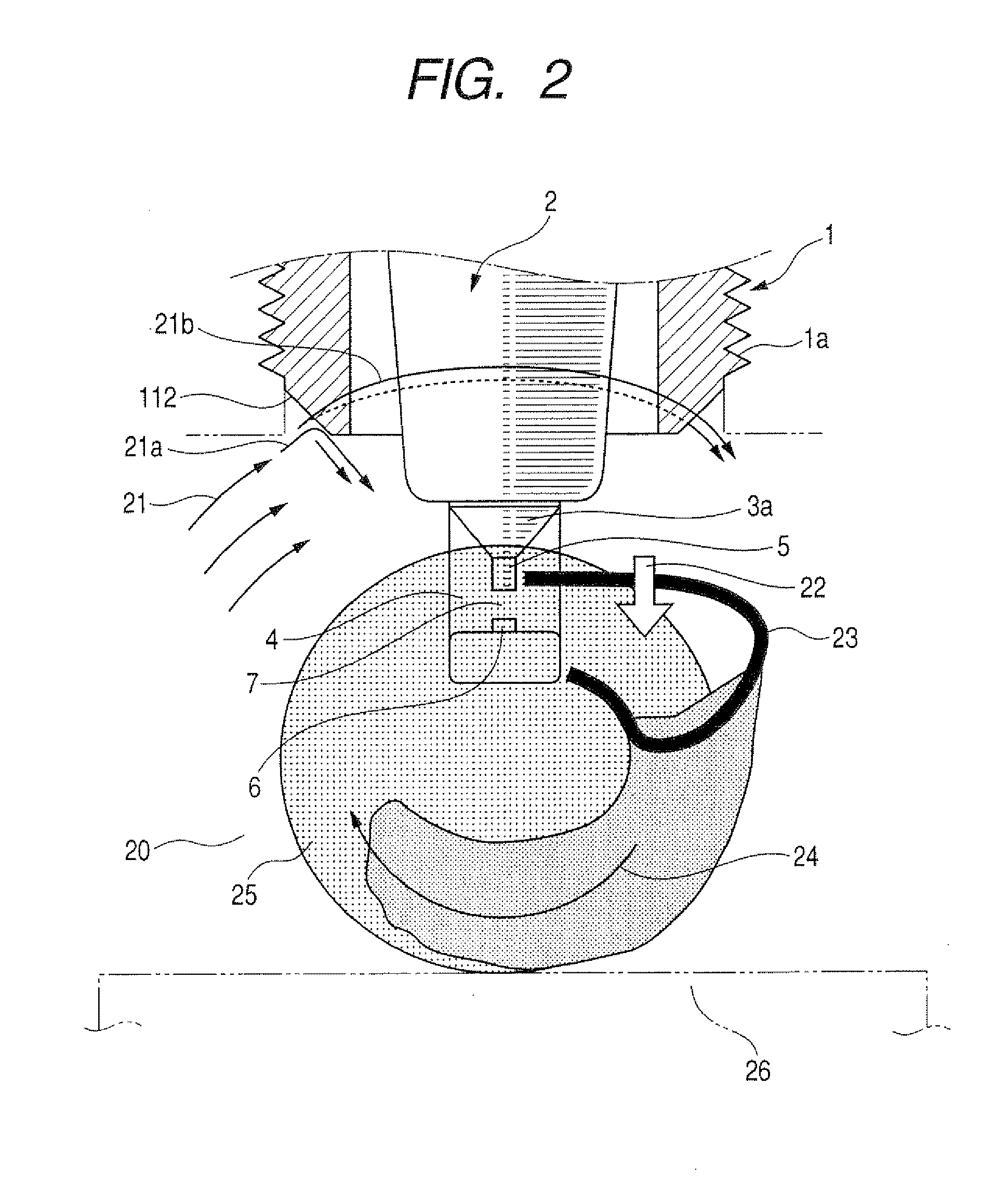
[0008]It is another object of the invention to provide a spark plug for internal combustion engines such as automotive gasoline engines which is designed to shape tumble vortexes of air-fuel mixture into streams oriented to a central portion of a combustion chamber of the engine, thereby ensuring the stability of flow of sparks to enhance the ignitability of the mixture.
[0014]The slant portion of the outer periphery of the top end portion defining the stream shaper may have a width W2 in a lateral direction perpendicular to the longitudinal center line of the metal housing which is 0.5 mm or more. A ratio of the width W2 to a width W1 of the top surface of the top end portion in the lateral direction (W2 / W1) is in a range of 0.5 to 1.0. This ensures the size of the slant portion which is great enough to orient the vortex streams to the central portion of the combustion chamber.

Problems solved by technology

In typical internal combustion engines, streams of air-fuel mixture flowing through parts of the spark plug such as the center electrode and the ground electrode exposed to a combustion chamber of the engine are usually disturbed by tumble vortexes of the air-fuel mixture, thus resulting in the instability in creating a sequence of sparks between the center and ground electrodes.
This leads to instability of size or orientation of the sparks.
The flame of the mixture, as created in the combustion chamber, may be undesirably cooled or dispersed depending upon the orientation of a flow of the spark, thus resulting in undesired form of the flame which contributes to poor ignition of the mixture.

Method used


Image

  • Spark plug with stream shaper to shape tumble vortex into desired stream in combustion chamber
  • Spark plug with stream shaper to shape tumble vortex into desired stream in combustion chamber
  • Spark plug with stream shaper to shape tumble vortex into desired stream in combustion chamber

Examples


Embodiment Construction

[0031]Referring to the drawings, wherein like reference numbers refer to like parts in several views, particularly to FIG. 8, there is shown a spark plug 100 which may be used in internal combustion gasoline engines for automotive vehicles.

[0032]The spark plug 100 includes a cylindrical metal housing or shell 1, a porcelain insulator 2, a center electrode 3, and ground electrode 4.

[0033]The metal shell 1 is made of a hollow metallic cylinder and has cut therein a thread 1a for mounting the spark plug 100 in an engine block (not shown).

[0034]The porcelain insulator 2 made of an electrically insulating material such as alumina is retained coaxially within the metal shell 1. The metal shell 1 has an upper annular extension 1b crimped inwardly to hold the porcelain insulator 2 firmly therewithin. The center electrode 3 to which a high voltage is to be applied is fit in a center through hole 2a of the porcelain insulator 2. In other words, the center electrode 3 is disposed in the metal ...


PUM


Abstract

A spark plug for an internal combustion engine is provided which includes a hollow cylindrical metal shell with an open end portion to be exposed to a combustion chamber of the engine, a ground electrode joined to the metal shell, a center electrode disposed in the metal housing to define a spark gap between itself and the ground electrode. The spark plug also includes a stream shaper geometrically formed on an outer periphery of the open end portion of the metal shell to shape tumble vortexes of air-fuel mixture into vortex streams oriented toward a central portion of the combustion chamber. This ensures the stability of orientation of the tumble vortexes to control a flow of sparks, thereby enhancing the ignitability of the air-fuel mixture in the combustion chamber.

Description

CROSS REFERENCE TO RELATED DOCUMENT[0001]The present application claims the benefit of Japanese Patent Application No. 2006-288200 filed on Oct. 24, 2006, the disclosure of which is incorporated herein by reference.BACKGROUND OF THE INVENTION[0002]1. Technical Field of the Invention[0003]The present invention relates generally to a spark plug for internal combustion engines such as automotive gasoline engines, and more particularly to an improved structure of such a spark plug equipped with a stream shaper working to shape tumble vortexes into streams oriented inside a combustion chamber of the engine to enhance the ignitability of air-fuel mixture.[0004]2. Background Art[0005]There have been proposed various types of spark plugs designed to have improved structures and materials of a center electrode and / or a ground electrode for enhancing the ignitability of air-fuel mixture within a combustion chamber of the engine. For example, Japanese Patent First Publication No. 2005-63705 te...

Claims


Application Information

Patent Timeline
IPC IPC(8): H01T13/02
CPCH01T13/18H01T13/32H01T13/20
Inventor HANASHI, KENTAKEUCHI, TAKAYUKI
Owner DENSO CORP
Learn More