
Nanofocus x-ray tube

a x-ray tube and focus technology, applied in the direction of x-ray tubes, electric discharge tubes, electrical equipment, etc., can solve the problems of affecting the quality of images, affecting the reliability of production, etc., and achieve the effect of more economical production and simplified construction

Inactive Publication Date: 2008-04-17
COMET
View PDF5 Cites 43 Cited by
  • Summary
  • Abstract
  • Description
  • Claims
  • Application Information

AI Technical Summary

Benefits of technology

[0008] The object of the invention is to create a nanofocus x-ray tube of the kind set forth in the preamble of claim 1 that achieves the generation of the small focal point diameter ≦1,000 nm required for high-resolution inspection of components by providing a simplified construction and hence more economical manufacture.

Problems solved by technology

As a result electrical charges, for instance electrons, may be drained off the target and thereby electrical target charging, which degrades image quality, is reliably precluded.

Method used


Image

  • Nanofocus x-ray tube
  • Nanofocus x-ray tube
  • Nanofocus x-ray tube

Examples


first embodiment

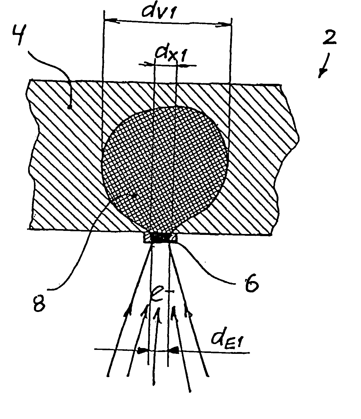
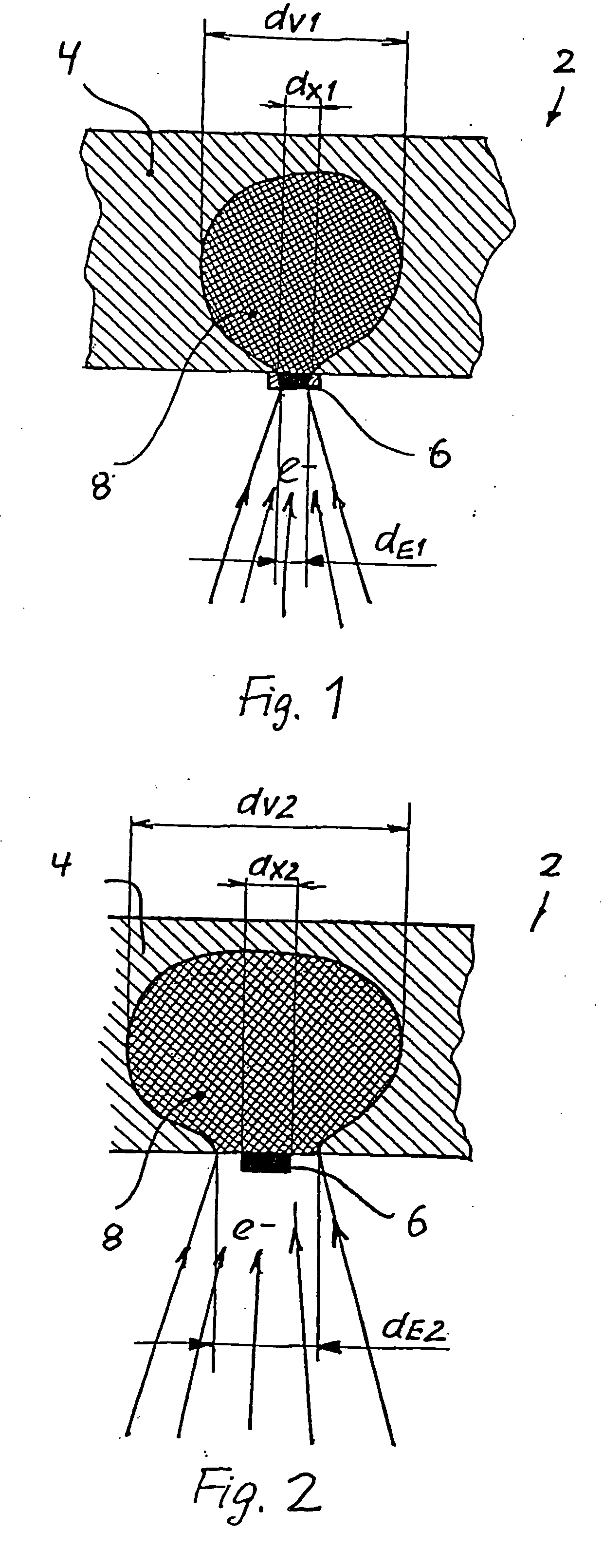
[0039]FIG. 1 shows a nanofocus x-ray tube's target 2 including a substrate element 4, and which in this embodiment, includes an x-ray emitting target element 6 mounted to the substrate element 4 and made of a target material. The substrate element 4 is principally made of a substrate material of low density and high heat conductivity, namely diamond, of which the heat conductivity is ≧20 W / (cm×° K).

[0040] In accordance with the invention, the diamond used as substrate material is doped, in the present embodiment with metal ions, to increase its electrical conductivity. Because doping renders the substrate material electrically conductive, electric charges are able to drain off the substrate element 4, so that electric charging of the substrate element 4 and hence of the target 2 is avoided.

[0041] The target element 6 consists of a material of high density, in the present embodiment tungsten, which emits x-rays when being bombarded with electrically charged particles, in particular ...

second embodiment

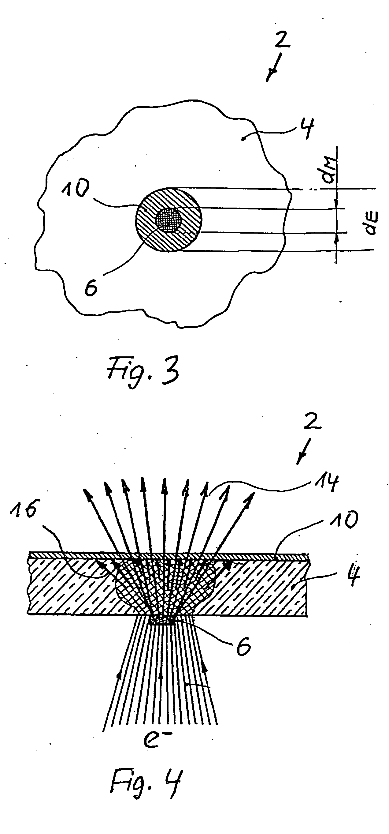
[0048]FIG. 4 shows a target 2 of the invention configured as a transmission target which differs from the embodiment of FIG. 1 in that the substrate element 4 is provided on its side facing away from the target element 6 with a beam filter 12 which is substantially transparent to the x-ray radiation 14 generated in the target element 6 but substantially opaque / absorbing with respect to the x-ray radiation 16 generated in the substrate element 4. Illustratively the filter 12 may be an aluminum sheet.

[0049] In FIG. 5, a preset electron beam cross-section is denoted by 10 whereas the reference numeral 18a therein denotes an electron beam cross-section that was reduced on account of interference and 18b denotes an electron beam cross-section that was enlarged on account of interference. The x-ray tube's focal point cross-section depending only on the cross-section of the target element 6, and latter being constant, fluctuations in electron beam cross-section do not affect focal point cr...


PUM


Abstract

Nanofocus x-ray tube, includes a target, and a device for directing an electron beam onto the target. The target includes at least one target element made of a target material for generating x-rays, the at least one target element including a nanostructure having a diameter ≦about 1000 nm. The nanostructure is formed by a microstructuring procedure on a substrate element made of a substrate material, and the target element only partly covers the substrate element. The electron beam cross-section of the x-ray tube, in use, is selected to be sufficiently larger than the cross-section of the target element, such that the electron beam always irradiates the entire surface of the target element. Still further, the substrate material may be diamond, or the substrate material may include diamond, and being doped to raise the electrical conductivity.

Description

CROSS-REFERENCE TO RELATED APPLICATIONS [0001] This application claims priority of German application no. 10 2005 053 386.8, filed Nov. 7, 2005, and which is incorporated herein by reference. FIELD OF THE INVENTION [0002] The present invention relates to a nanofocus x-ray tube as defined in the preamble of claim 1. BACKGROUND OF THE INVENTION [0003] Nanofocus x-ray tubes of this kind are generally known. They include a target and means to direct an electron beam onto the target. For example, as regards imaging, they are used in high-resolution inspection of components such as printed circuit boards used in electronics. In order to achieve high spatial resolution in such imaging procedures, the electron beam of known nanofocus x-ray tubes is shaped in a manner that at incidence on the target, a focal point having a diameter ≦1,000 nm is formed. [0004] Nanofocus x-ray tubes generating such small electron beam diameters are known which operate on the principle of x-ray diffraction and ...

Claims


Application Information

Patent Timeline
Patent Type & Authority Applications(United States)
IPC IPC(8): H01J35/14
CPCH01J35/08H01J2235/087H01J2235/081H01J35/12H01J35/116H01J2235/083
Inventor REINHOLD, ALFRED
Owner COMET
Learn More