
Rack for containers

a technology for containers and racks, applied in the field of racks for holding objects, can solve the problems of relative movement, leakage of containers, and leaking containers, and achieve the effect of improving the stability and stacking of layers

Inactive Publication Date: 2008-04-10
REHRIG PACIFIC CO INC
View PDF50 Cites 17 Cited by
  • Summary
  • Abstract
  • Description
  • Claims
  • Application Information

AI Technical Summary

Benefits of technology

This invention relates to a rack system used for storing items. It features multiple levels with spaces between them where objects can be placed. There are also columns connecting the different sections of the rack. These columns have special parts called interlocking members that fit together like pieces of a jigsaw puzzle when two racks are stacked on top of each other. This design makes it easier to stabilize and organize the rack's contents. Additionally, some of the spaces between the rows may contain elastic materials to protect sensitive components from damage during transportation.

Problems solved by technology

The technical problem addressed in this patent text is how to prevent leakage of water bottles during deliveries due to the bouncing motion experienced while driving through uneven surfaces. This issue was previously caused mainly by traditional metal racks, which were now being replaced with lightweight plastic versions to save cost. However, these new plastic racks may not provide enough protection against leaks, especially when carrying soft-bodied bottles.

Method used


Image

  • Rack for containers
  • Rack for containers
  • Rack for containers

Examples


Embodiment Construction

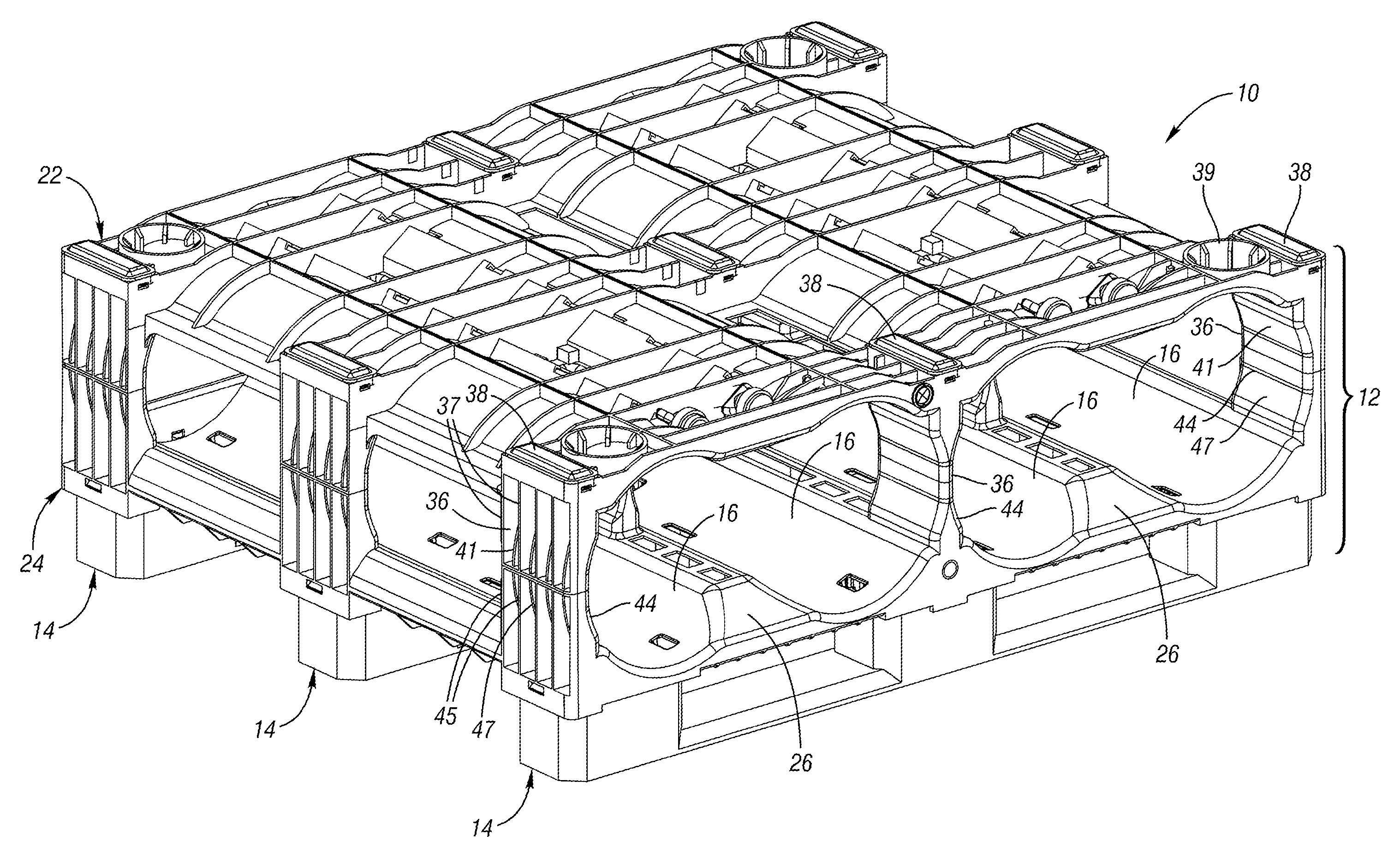
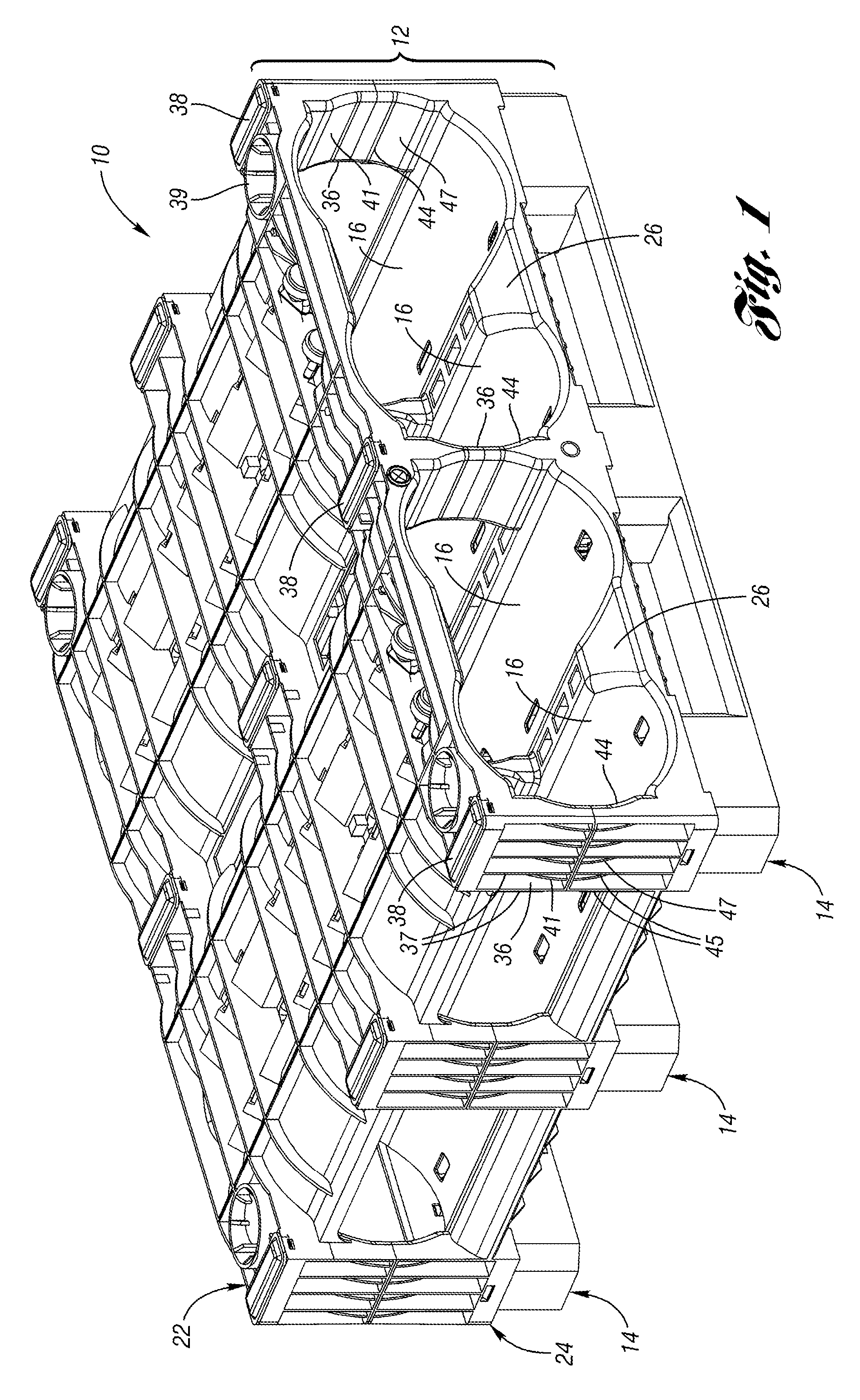
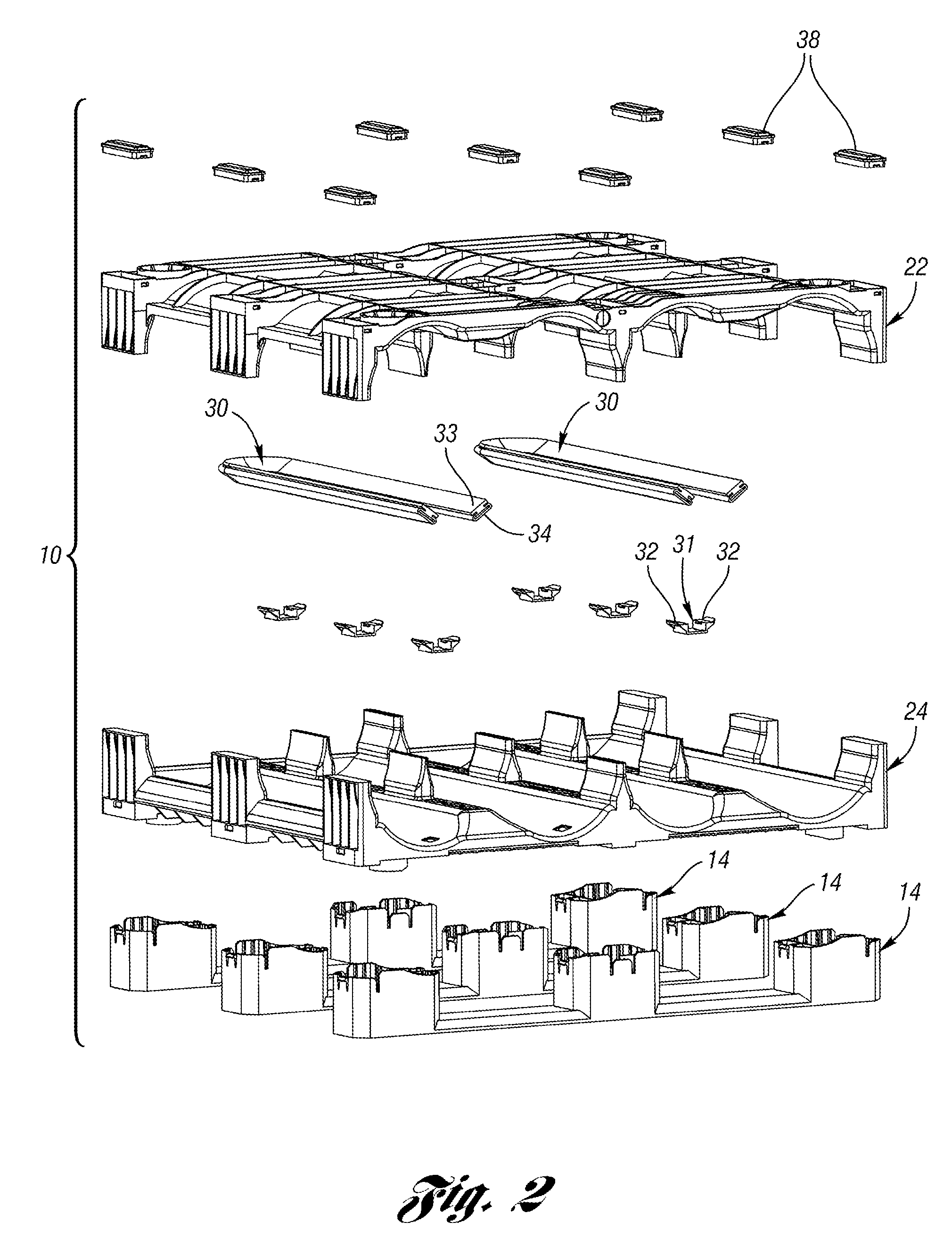
[0025]FIG. 1 is a perspective view of a rack 10 according to one embodiment of the present invention. The rack 10 includes a first layer 12 (or first “shelf”) supported on a plurality of supports 14. The first layer 12 defines a plurality of generally cylindrical bays 16. A pair of five gallon water bottles (not shown) can be received within each bay 16. The first layer 12 includes an upper section 22 and a lower section 24. The lower section 24 includes a partial divider 26 between each adjacent pair of bays 16.

[0026]The upper section 22 has a plurality (in this example, nine) of column portions 36, each having a support pad 38 thereon. In this example, the support pads 38 are tapered blocks snap fit to the top of the column portions 36. The support pads 38 ensure alignment of another layer stacked thereon, although the actual weight is transferred directly to the column portions 36, not on the support pads 38. The outer ones of the column portions 36 including a plurality of verti...


PUM


Abstract

A rack for securing containers includes a plurality of bays into which one or more containers are received. The rack includes an upper section and a lower section defining a bay therebetween. The bay has a concave support surface for supporting an object. A plurality of columns connect the upper section to the lower section. The upper section and the lower section each include a plurality of complementary interlocking members aligned with the plurality of columns, such that the interlocking members on the upper section would interlock with the interlocking members on the lower section of a similar rack stacked thereon. Each bay may include a resilient member, such as an expandable clamp or a resilient bumper.

Description


Claims


Application Information

Patent Timeline
Owner REHRIG PACIFIC CO INC
Learn More