
Dust collector

a dust collector and dust collector technology, applied in the field of dust collectors, can solve the problems of inability to completely the dust collector cannot overcome the clogging problem, and the clogging cannot be completely overcome by these methods, so as to prevent the clogging of the filter, suppress the flow of dust, and efficiently collect and recover the fume produced

Inactive Publication Date: 2008-04-10
ANLET CO LTD
View PDF2 Cites 51 Cited by
  • Summary
  • Abstract
  • Description
  • Claims
  • Application Information

AI Technical Summary

Benefits of technology

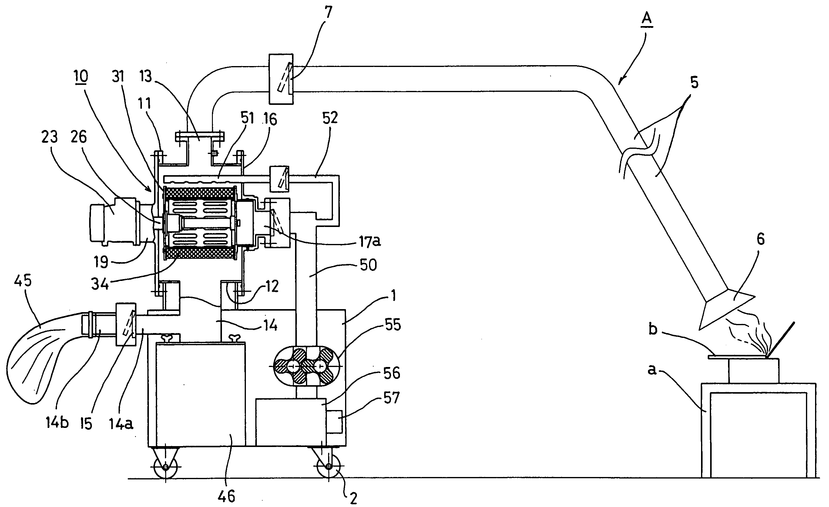
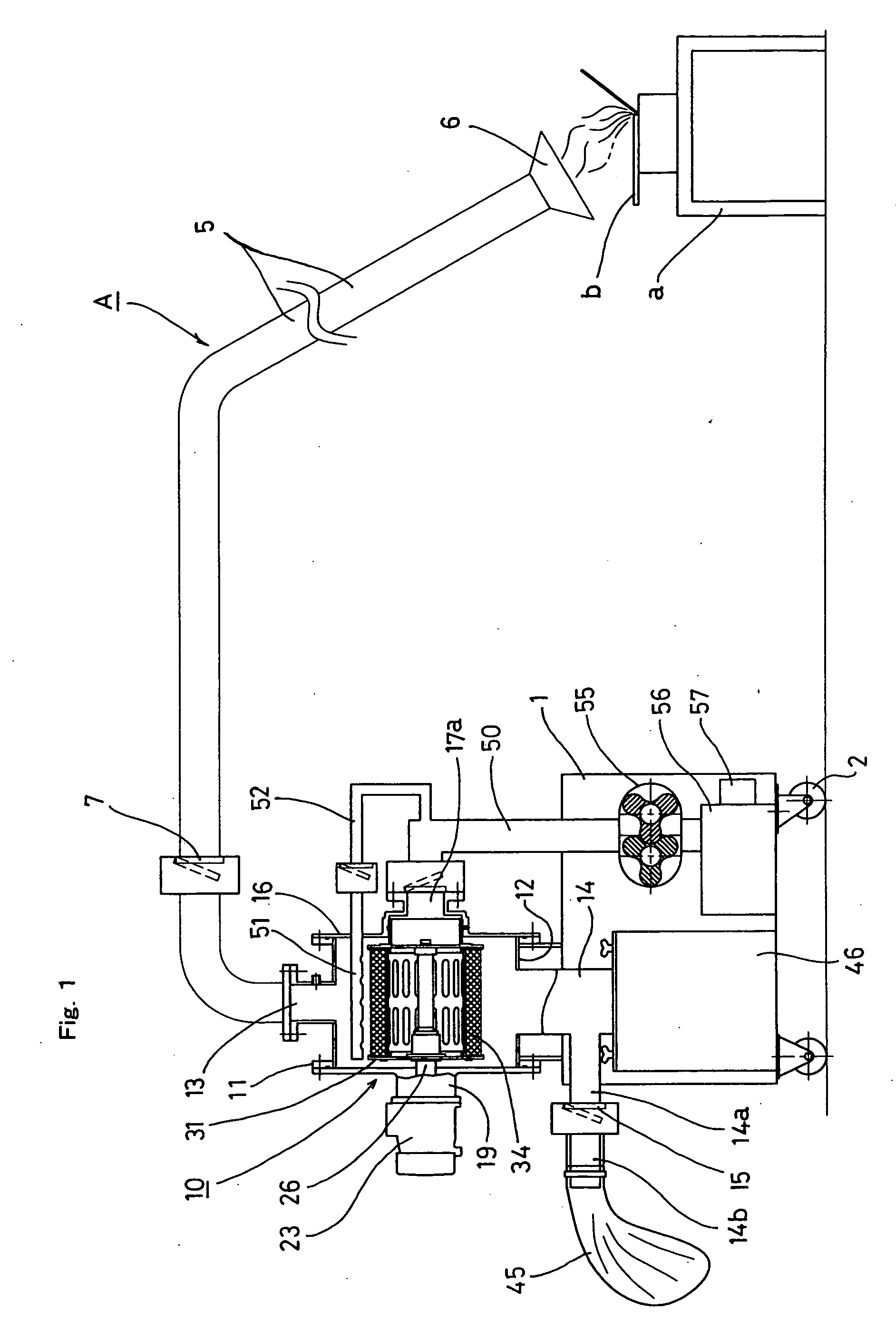
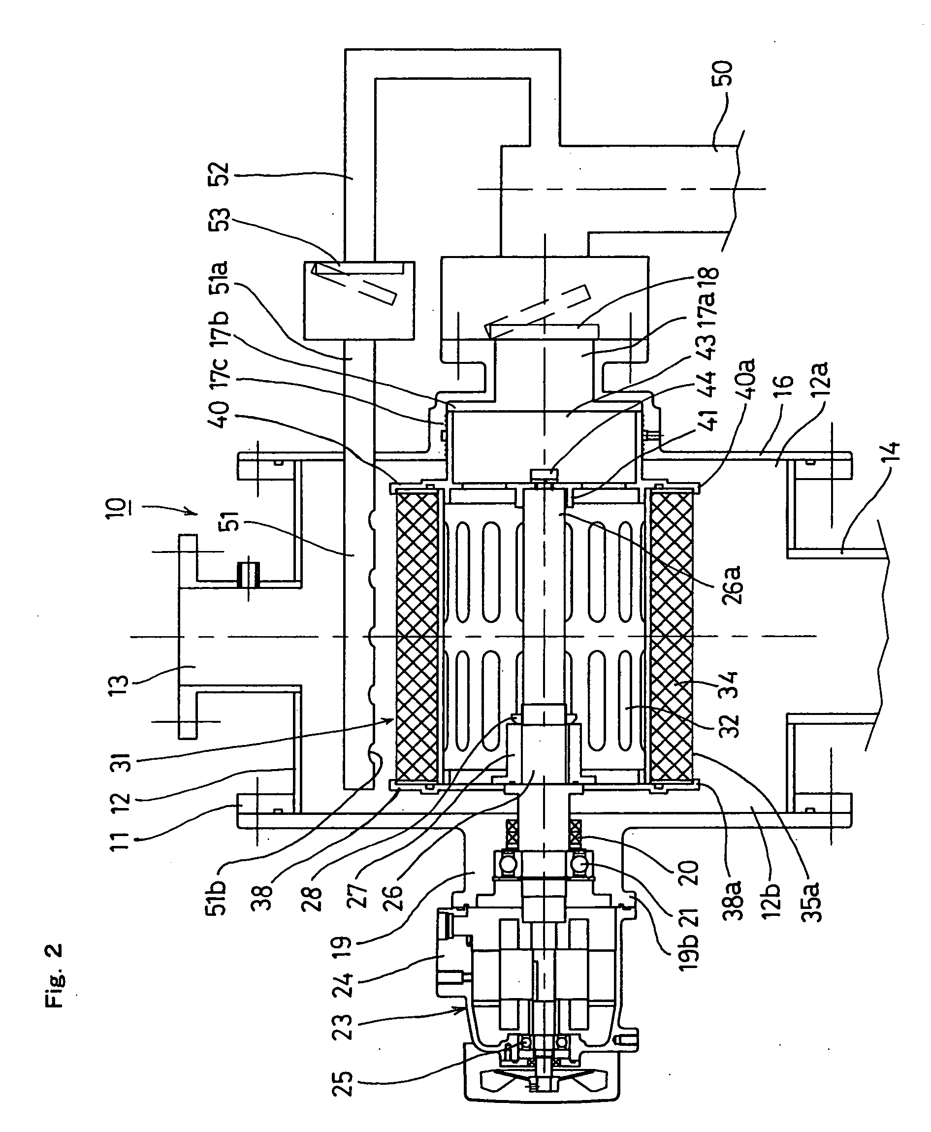
[0017]As the result of a compact combination of the collection unit using the rotary filter and the Roots blower, the above-described construction can efficiently collect and recover viscous fume produced rustproof oil or paint applied to iron material to be welded in an arc-welding work, minute dust and / or mist produced by cutting machines, grinding machines or the like. Furthermore, since pressure air is blown against the rotary filter by the air blow nozzle so that dust and / or the like adherent to the filter is removed, the filter can be maintained in a desired state.
[0018]In another form, the dust collector further comprises a recovery tank detachably attached to the lower part of the case, instead of the recovery bag. Since the collected dust is stored in the recovery tank, the post treatment of dust can easily be carried out.
[0019]In further another form, the dust collector further comprises a detachable tank provided between the suction pipe and the collection unit, the detachable tank incorporated with a cyclone which is formed into a shape flaring out at a bottom thereof. This dust collector has such a construction as to be capable of collecting, in the detachable tank, carbon, oil component, clouds of dust or the like produced by road sweeping by a unimog. Since this construction suppresses flow of dust or the like into the collection unit, the filter can be prevented from clogging.
[0021]As the result of a compact combination of the collection unit using the rotary filter and the Roots blower, the above-described construction can collect non-viscous light fume at a high efficiency of about 99% without a large installation space. Furthermore, since pressure air is blown against the rotary filter by the air blow nozzle so that dust and / or the like adherent to the filter is removed, the filter can be maintained in a desired state.

Problems solved by technology

General filter dust collectors use filters with mesh ranging from 0.1 μm to 0.5 μm but are susceptible to clogging.
However, the problem of clogging cannot be overcome by these methods completely.
However, the conventional filter dust collector cannot overcome clogging due to fume containing oil component or viscous fume and cannot maintain a desirable collecting performance.
When any method is employed, it would be difficult to achieve amenity in working environment, safety in workers' health or normal operation of processing machinery and equipment which produce mist, or to prevent contamination of circumjacent buildings, unless produced mist is efficiently treated.
Furthermore, non-viscous light dust is produced in the process of plastics, paper or wood.
As a result, the dust collector sometimes has a definite limitation in the service space.
However, since a plurality of filter units are used in the dust collector, replacement costs of the filter units are increased.

Method used


Image

  • Dust collector
  • Dust collector
  • Dust collector

Examples


experiment 1

[0050]Experiment 1 was conducted under the following conditions regarding the performance of collecting viscous fume (wet fume) produced during welding of a weld iron material to which rustproof oil or paint has been applied and pressure loss between the suction hood and the suction opening of the Roots blower. Comparative examples 1 to 3 were involved in the experiment. FIGS. 8 and 9 are graphs showing the results of the experiment. TABLE A describes the dust collector A used in the experiment 1.

TABLE 1Dust collector ACollection unitFilter:Synthetic non-woven cloth was used asfilter material. 0.3-μm mesh,diameter of 200 mm × length of 200 mmRotational speed1000 rpmof filter:Motor output:0.4 kwRoots blower:Bore diameter of 50 mm × output of 1.5 kw,rotational speed of 2500 rpmair discharge rate of 1.5 m3 / minAmount of produced wetAbout 20 mg / m3fume:

[0051]In the embodiment, the filter was cleaned repeatedly by an air blow nozzle using wet fume.

[0052]FIG. 8 shows results of the experime...

experiment 2

[0068]Experiment 2 was conducted under the following conditions regarding the collecting performance of the dust collector B and pressure loss between the suction hood and the suction opening of the Roots blower. Wheat flour was used to resemble dust in experiment 2. More specifically, wheat flour contained in a container was flung up by pressure air used in a factory. FIG. 14 is a graph showing the results of the experiment. TABLE 2 describes the dust collector B used in the experiment.

TABLE 2Dust collector BCollection unitFilter:Three types of 0.3-μm mesh, 3-μm mesh and10-μm meshdiameter of 200 mm × length of 200 mm × surfacearea of 1.2 m2Rotational speed1500 rpm in the suction and 150 rpm in theof filter:cleaningMotor output:0.4 kwRoots blowerBore diameter of 50 mm × output of 1.5 kw,Rotational speed:3000 rpm in the suction and 1800 rpm inthe cleaningAir discharge rate:2.2 m3 / min in the suction and 1.0 m3 / minin the cleaningPressure:−10 kPa in the suction and +30 kPa in theCleanin...


PUM

PropertyMeasurementUnit
particle sizeaaaaaaaaaa
particle diameteraaaaaaaaaa

Abstract

A dust collector includes a collection unit including a suction pipe and a Roots blower outwardly discharging the air having passed through the collection unit. The collection unit further includes a rotational shaft rotatably mounted in a housing of the case and disposed so as to face an interior of the case, a rotary filter mounted on the shaft and including a cylindrical porous core and a filter material attached to an outer circumference of the core and having a number of folds made of nonwoven cloth with a mesh into a continuous zigzag shape, an air blower nozzle blowing on an outer surface of the rotary filter pressure air produced by drive of the blower in a reverse direction thereby to clean the filter, and a recovery bag accommodating the dust or the like removed from the rotary filer during cleaning by the air blower nozzle.

Description

CROSS-REFERENCE TO RELATED APPLICATIONS[0001]This application is based upon and claims the benefit of priority from the prior Japanese Patent Application Nos. 2006-272909 filed on Oct. 4, 2006 and 2006-288510 filed on Oct. 24, 2006, the entire contents of both of which are incorporated herein by reference.BACKGROUND OF THE INVENTION[0002]1. Field of the Invention[0003]The present invention relates to a dust collector suitable for collecting or recovering fume produced during arc-welding, minute dust and / or mist produced by cutting machines, grinding machines or the like, carbon, oil component, clouds of dust or the like produced by road sweeping by a unimog and minute dust produced in the process of manufacturing foodstuff such as wheat flour, non-viscous light dust or the like resulting from machining of plastics, paper or wood.[0004]2. Description of the Related Art[0005]Arc-welding of welding iron material to which rustproof oil or paint is applied produces minute fume of 100 ang...

Claims


Application Information

Patent Timeline
Patent Type & Authority Applications(United States)
IPC IPC(8): B01D46/00
CPCB01D46/0056B01D46/26B01D46/0089B01D46/0065B01D46/682B01D46/00
Inventor YOKOI, YASUNAKATO, TOSHIAKITAKEDA, MASAFUMIITO
Owner ANLET CO LTD
Learn More