
Electrode array structures and methods of use for cardiovascular reflex control

a technology of electromechanical array and electrode array, which is applied in the direction of internal electrodes, spinal electrodes, therapy, etc., can solve the problems of heart failure and stroke, increase in blood pressure, and serious health problems, so as to optimize patient's response, save battery usage, and reduce power.

Active Publication Date: 2008-04-03
CVRX
View PDF47 Cites 95 Cited by
  • Summary
  • Abstract
  • Description
  • Claims
  • Application Information

AI Technical Summary

Benefits of technology

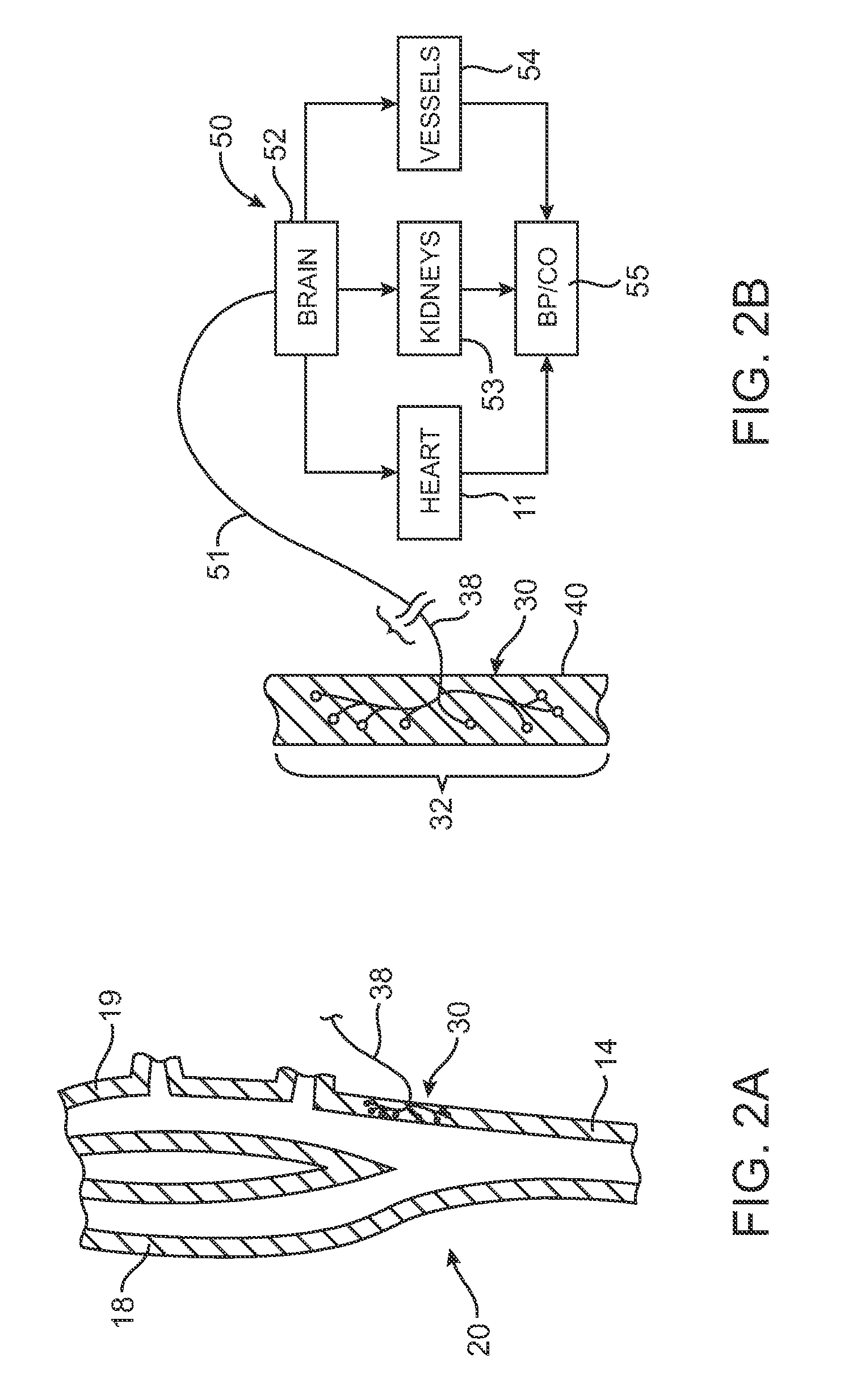
[0017]A method and apparatus is disclosed for providing a baroreflex treatment that modulates the blood pressure of a patient by electrically stimulating a vessel wall, such as an artery or vein. A baroreflex activation device comprises an array of electrodes that are adapted to reduce the need to reposition the electrode array during surgery by allowing multiple selectively activatable electrode patterns. The baroreflex activation device is combined with a control system to automatically create a map of a patient's response to baroreflex stimulation and allow the device to be configured or reconfigured to optimize the patient's response. Further, the device allows the stimulation pattern to be adjusted or modified after implantation to account for any changes in the effectiveness of the treatment.
[0021]In one embodiment, the sub-stimulation test signals used to determine an optimum combination of electrodes in the electrode array include a high frequency signal that is delivered to a predetermined combination of electrode arrangements. The capacitance, inductance, resistance and / or reflectance of the high frequency signals are sampled for each test pattern combination to automatically create a sub-stimulation map of the anticipated responsiveness of each test pattern combination. Because the sub-stimulation map can be created without the required delay to determine the patient's physiological responsiveness to a given level of stimulation pulses for each given test pattern combination of electrodes, the present invention provides an improved approach for utilizing an electrode array as part of the electrode assembly of a baroreflex activation device.
[0025]In another embodiment, the baroreflex activation device comprises a flexible base and an array of multi-pole electrodes that are independently activatable. Multi-pole electrodes comprise a center portion surrounded by two or more electrically conductive rings. Activation of a multi-pole electrode, such as between the center and an outer ring or between the inner ring and the outer ring, creates a spatially limited electric field. Such an activation can assist in controlling the depth of stimulation, so as to stimulate different tissues at different depths. Various parameters of such a multi-polar electrode embodiment may be modified or adjusted to affect the shape and penetrating depth of the stimulating electric field so as to provide the desired baroreflex therapy. In one aspect of this embodiment, the polarity is switchable between the various parts of the multi-polar electrode. For example, the center portion may comprise an anode, while the surrounding concentric rings comprise cathodes, or vice versa. The inner ring may comprise a cathode while the outer ring and central portion comprise anodes.
[0027]In another embodiment of the present invention, the control signal generated by the control system comprises multiple successive pulses. In contrast to a control signal comprising a pulse waveform having a large amplitude, multiple pulses of smaller amplitude, called a pulse series, are fired in succession. Each pulse in the pulse series has a smaller amplitude, thereby yielding a similarly effective result to the large single pulse, however less power is required, thereby conserving battery usage. The pulse series may be fired between the same anode-cathode combination, or unique anode-cathode combinations may be used for each pulse in a pulse series. Similarly, successive pulse series may comprise identical or varied anode-cathode firing combinations. In an embodiment where each pulse in a pulse series fires between unique anode-cathode combinations, each successive pulse in the series may be staggered so as to overlap. Alternatively, each successive pulse in the series may be staggered such that there is no overlap between pulses.
[0028]To address hypertension and other conditions requiring blood pressure augmentation, the present invention provides electrode designs and methods configured to reduce the need to reposition an electrode activation device during surgery. By allowing multiple selectively activatable electrode patterns and combining the baroreflex activation device with a control system, the present invention can automatically create a map of a patient's response to baroreflex stimulation and allow the device to be configured or reconfigured to optimize the patient's response.

Problems solved by technology

Cardiovascular disease is a major contributor to patient illness and mortality.
It also is a primary driver of health care expenditure, costing billions of dollars each year in the United States.
Hypertension is a leading cause of heart failure and stroke.
It is the primary cause of death for tens of thousands of patients per year and is listed as a primary or contributing cause of death for hundreds of thousands of patients per year in the U.S. Accordingly, hypertension is a serious health problem demanding significant research and development for the treatment thereof.
Hypertension occurs when the body's smaller blood vessels (arterioles) constrict, causing an increase in blood pressure.
Because the blood vessels constrict, the heart must work harder to maintain blood flow at the higher pressures.
Although the body may tolerate short periods of increased blood pressure, sustained hypertension may eventually result in damage to multiple body organs, including the kidneys, brain, eyes and other tissues, causing a variety of maladies associated therewith.
The elevated blood pressure may also damage the lining of the blood vessels, accelerating the process of atherosclerosis and increasing the likelihood that a blood clot may develop.
This could lead to a heart attack and / or stroke.
Sustained high blood pressure may eventually result in an enlarged and damaged heart (hypertrophy), which may lead to heart failure.
It is characterized by an inability of the heart to pump enough blood to meet the body's needs and results in fatigue, reduced exercise capacity and poor survival.
Heart failure results in the activation of a number of body systems to compensate for the heart's inability to pump sufficient blood.
The cardiac, renal and vascular responses increase the workload of the heart, further accelerating myocardial damage and exacerbating the heart failure state.
Another challenge related to the positioning process is the task of keeping track of previous desirable positions.
Returning the electrode assembly to a previously-observed optimal position can be quite difficult and frustrating, especially under surgical conditions.
Loosening or removing the sutures, re-positioning the electrode assembly, and tightening or re-installing the sutures can increase the time and costs associated with the devices, and can also increase the risk of complications or surgeon errors related to protracted surgical procedures and fatigue.
While effective, this process can become lengthy and involved as the number of combinations of electrode pairs or groups of pairs being tested increases or if the electrode array is repositioned along the carotid sinus.
A further challenge facing current implantable baroreflex treatment devices is power usage.
However, this negatively impacts battery life.

Method used


Image

  • Electrode array structures and methods of use for cardiovascular reflex control
  • Electrode array structures and methods of use for cardiovascular reflex control
  • Electrode array structures and methods of use for cardiovascular reflex control

Examples


Embodiment Construction

[0050]The following detailed description should be read with reference to the drawings in which similar elements in different drawings are numbered the same. The drawings, which are not necessarily to scale, depict illustrative embodiments and are not intended to limit the scope of the invention.

[0051]To better understand the present invention, it may be useful to explain some of the basic vascular anatomy associated with the cardiovascular system. Refer to FIG. 1 which is a schematic illustration of the upper torso of a human body 10 showing some of the major arteries and veins of the cardiovascular system. The left ventricle of the heart 11 pumps oxygenated blood up into the aortic arch 12. The right subclavian artery 13, the right common carotid artery 14, the left common carotid artery 15 and the left subclavian artery 16 branch off the aortic arch 12 proximal of the descending thoracic aorta 17. Although relatively short, a distinct vascular segment referred to as the brachioce...


PUM


Abstract

A tissue stimulation device includes an electrode array having at least four independently switchable electrodes. In one embodiment, the electrode array comprises a flexible base to which the electrodes are fixed that flexes to encompass at least a portion of an artery or other elongate biological structure. The electrodes are electrically coupled to and energized by a signal generator coupled to a control system. In one embodiment, the array of electrodes are configured such that a suitable signal pattern for stimulation pulses between or among a set of the switchable electrodes may be determined without having to reposition the electrode assembly by using a series of signal patterns activating different combinations of switchable electrodes in response to sub-stimulation test signals to determine a signal pattern that provides suitable patient response. In another embodiment, the array of electrodes includes an array of selectively activatable multi-polar electrodes.

Description

CROSS-REFERENCES TO RELATED APPLICATIONS[0001]This application claims the benefit of Provisional Patent Application No. 60 / 827,242, filed Sep. 28, 2006, the disclosure of which is hereby incorporated by reference in its entirety.BACKGROUND OF THE INVENTION[0002]This invention relates generally to implantable medical devices. More particularly, the present invention relates to methods and apparatus for utilizing an electrode assembly having an array of electrodes as part of a baroreflex activation device.[0003]Cardiovascular disease is a major contributor to patient illness and mortality. It also is a primary driver of health care expenditure, costing billions of dollars each year in the United States. Hypertension, or high blood pressure, is a major cardiovascular disorder that is estimated to affect 65 million people in the United Sates alone. Of those with hypertension, it is reported that fewer than 30% have their blood pressure under control. Hypertension is a leading cause of h...

Claims


Application Information

Patent Timeline
IPC IPC(8): A61N1/08
CPCA61N1/0551A61N1/0556A61N1/36117A61N1/36114A61N1/0558
Inventor KIEVAL, ROBERT S.ROSSING, MARTIN
Owner CVRX
Learn More