Eureka AIR delivers breakthrough ideas for toughest innovation challenges, trusted by R&D personnel around the world.

Method and System for Performing Timing Recovery in a Digital Communication System

a digital communication system and timing recovery technology, applied in pulse manipulation, pulse technique, digital transmission, etc., can solve the problems of multipath problems, square wave pulses inserted at the transmit end of the channel suffer from roll-off, and the transmission of digital information presents many challenges

Inactive Publication Date: 2008-04-03
AVAGO TECH INT SALES PTE LTD
View PDF5 Cites 11 Cited by
  • Summary
  • Abstract
  • Description
  • Claims
  • Application Information

AI Technical Summary

Benefits of technology

The patent describes a system and method for processing signals in a communication system. The technical effects of this invention include improved signal processing, better data transmission, and enhanced network performance. These advantages can benefit various industries and applications that require reliable and efficient communication.

Problems solved by technology

Transmission of digital information presents many challenges.
One issue concerns recovering timing information about the transmitted signal.
Some other issues are related to the effects produced on the signal as a result of the channel characteristics.
As a result, a square wave pulse inserted at a transmit end of the channel suffers from roll-off at a receiving end of the channel.
In addition, the channel may also be plagued with multipath issues that manifest themselves as reflections of the original signal being added to the original signal.
As a result of these characteristics, there may be a significant amount of inter-symbol-interference (ISI) seen at the receiving end of the channel.
However, this quick response time is obtained at the expense of a computationally demanding process that becomes more demanding as the data rates increase.
When the data rates are higher, for example in the 10 Gbit / sec range, the time-domain LMS technique may become too computationally demanding and perhaps too costly.
The problem with this technique however, is that it does not have any constraint for the pre-cursor.
This will result in a non-zero contribution during the frequency domain FIR computation and will thus result in the loss of accurate timing error information that could be derived based on the zero-crossing at the pre-cursor that is introduced by the pre-filter.

Method used


Image

  • Method and System for Performing Timing Recovery in a Digital Communication System
  • Method and System for Performing Timing Recovery in a Digital Communication System
  • Method and System for Performing Timing Recovery in a Digital Communication System

Examples


Embodiment Construction

[0019]Certain embodiments of the invention may be found in a method for processing signals in a communication system. Exemplary aspects of the invention may comprise equalizing a signal with a timing-recovery system using a frequency domain equalizer. The frequency domain equalizer may be a frequency domain adaptive filter that adapts using a least-mean-square algorithm where at least one tap-weight's adaptation that corresponds to a pre-cursor may be constrained to zero. The processing may include recovering timing information using a Mueller / Muller timing recovery algorithm that may be aided by using a pre-filter before the adaptive equalizer.

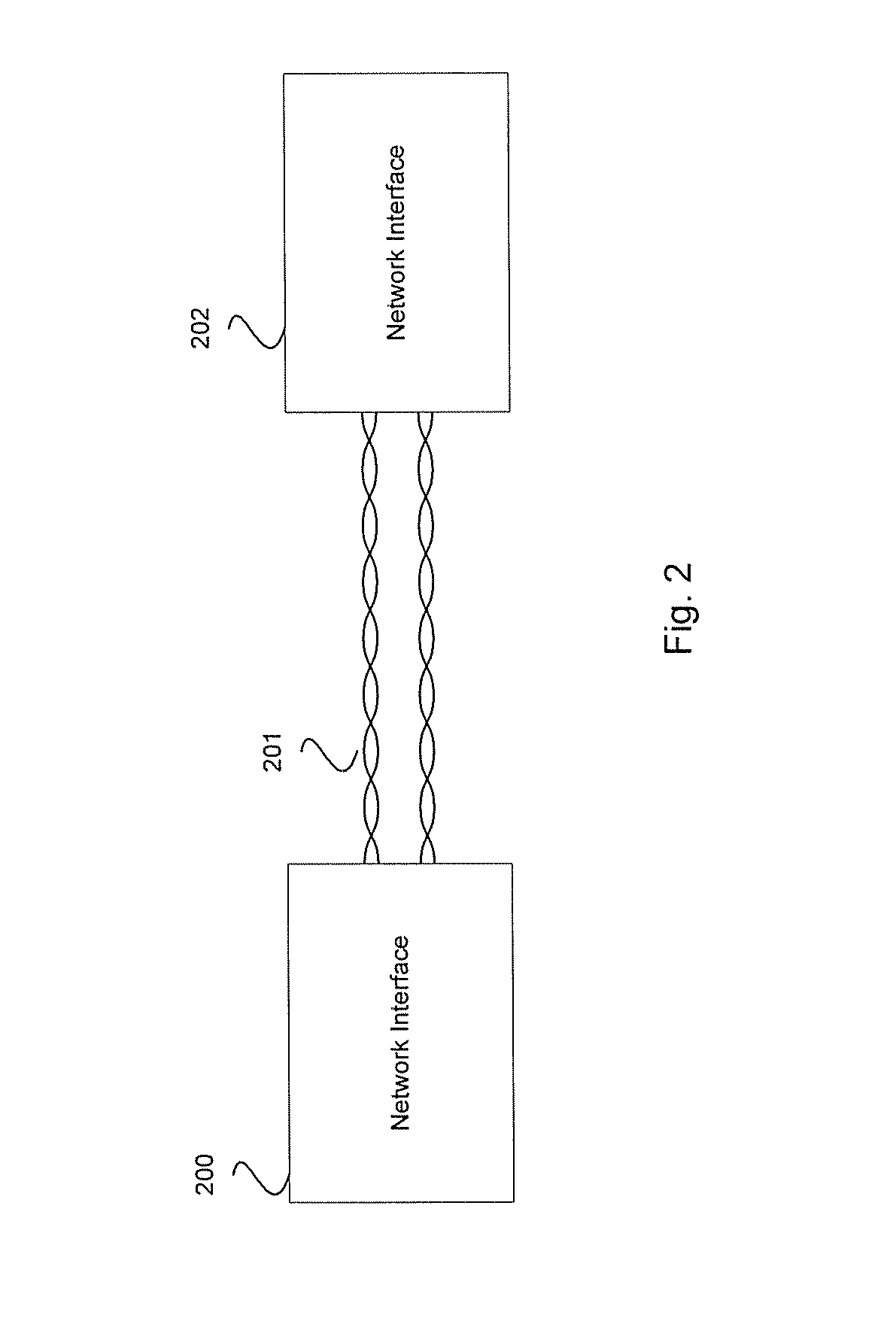
[0020]FIG. 1 is a diagram of two computers communicating over a network, which may be utilized in connection with an embodiment of the invention. Referring to FIG. 1, shown are two computers 100 and 101, a network connection 102, and two network interface cards 103 and 104. The computers 100 and 101 may comprise suitable logic, circuitry, and...


PUM


Abstract

Processing signals in a digital communication may include equalizing a signal in a timing-recovery system using a frequency domain equalizer. The frequency domain equalizer may be a frequency domain adaptive filter that adapts using a least-mean-square algorithm where at least one tap-weight that corresponds to a pre-cursor may be constrained to zero. The processing may include recovering timing information using a Mueller / Muller timing recovery algorithm that may be aided by using a pre-filter before the equalizer.

Description

CROSS-REFERENCE TO RELATED APPLICATIONS / INCORPORATION BY REFERENCE[0001]Not Applicable.FIELD OF THE INVENTION[0002]Certain embodiments of the invention relate to a method for processing signals in a communication system. More specifically, certain embodiments of the invention relate to a method and system for performing timing recovery in a digital communication system.BACKGROUND OF THE INVENTION[0003]Transmission of digital information presents many challenges. One issue concerns recovering timing information about the transmitted signal. This is necessary in order to properly sample the signal at the receiver. Some other issues are related to the effects produced on the signal as a result of the channel characteristics. The channel in a digital communication system may be characterized as a filter with a limited bandwidth. As a result, a square wave pulse inserted at a transmit end of the channel suffers from roll-off at a receiving end of the channel. In addition, the channel may...

Claims


Application Information

Patent Timeline
Patent Type & Authority Applications(United States)
IPC IPC(8): H03K5/159H04B1/10
CPCH04L7/0062
Inventor WANG, PEIQINGTAZEBAY, MEHMET V.POWELL, SCOTT
Owner AVAGO TECH INT SALES PTE LTD
Why Eureka
Eureka Blog
Learn More