
Mobile Phone

a mobile phone and image technology, applied in the field of mobile phones, can solve the problems of insufficient magnified image projection function, inability to achieve sufficient, and inability to project the above-described portable terminal devices and mobile phones, etc., and achieve bright and sharp projection images. , the effect of driving electric power

Inactive Publication Date: 2008-04-03
CITIZEN ELECTRONICS CO LTD
View PDF1 Cites 13 Cited by
  • Summary
  • Abstract
  • Description
  • Claims
  • Application Information

AI Technical Summary

Benefits of technology

[0015]Accordingly, an object of the present invention is to provide a mobile phone having an image projection function incorporated therein without impairing the portability thereof by enabling mounting of a projection lens larger in size than a specific region of a liquid crystal panel for forming an image for projection, with the size of the mobile phone kept from becoming much larger than that in the state of the art.
[0017]In this mobile phone, an image for image projection is formed by using a specific region in a part of a transmissive liquid crystal panel for information display. Therefore, even if a projection lens larger in size than the specific region is prepared, the lens can be accommodated in the mobile phone. Accordingly, a sharp and large image can be projected without impairing the portability of the mobile phone.
[0023]In a case where a separately prepared projection lens is adapted to be detachable with respect to the mobile phone body as stated above, it becomes possible to use a projection lens large in shape in comparison to the projection lens that is integrally attached to the mobile phone. The use of a separately prepared compact and detachable projection lens increases the number of alternatives to choose from in selecting a housing place of the projection lens in the mobile phone body and hence increases the design freedom of the mobile phone.
[0025]The charger enables supply of higher driving electric power and makes it possible to form a brighter and sharper projected image.

Problems solved by technology

The above-described portable terminal device and mobile phone, however, have no lens for projection.
Thus, a sufficient magnified image projection function cannot be attained.
Therefore, if a projection lens larger than the liquid crystal panel is installed in the mobile phone, the size of the mobile phone unavoidably needs to be increased, which will impair the portability of the mobile phone.

Method used


Image

  • Mobile Phone
  • Mobile Phone
  • Mobile Phone

Examples


first embodiment

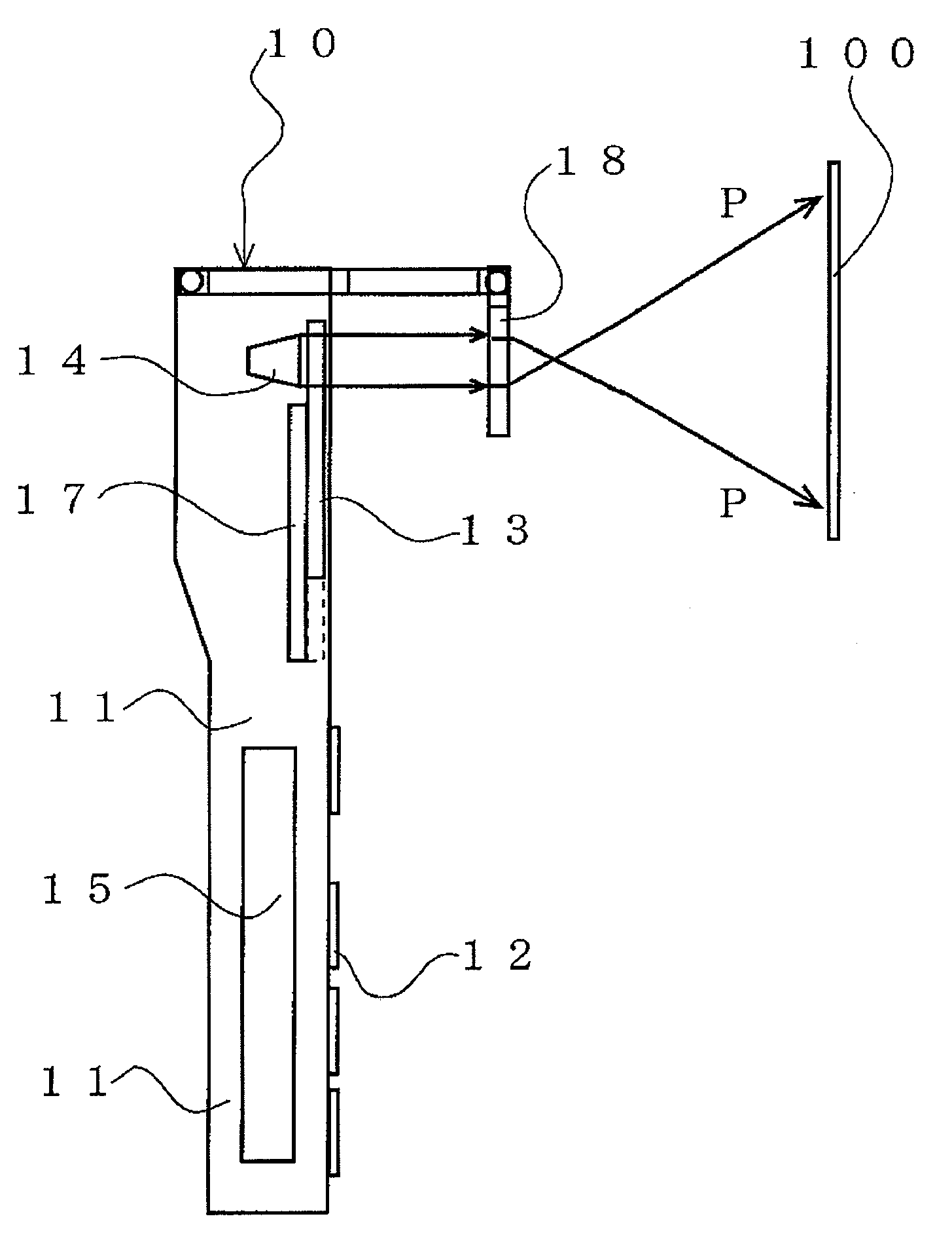
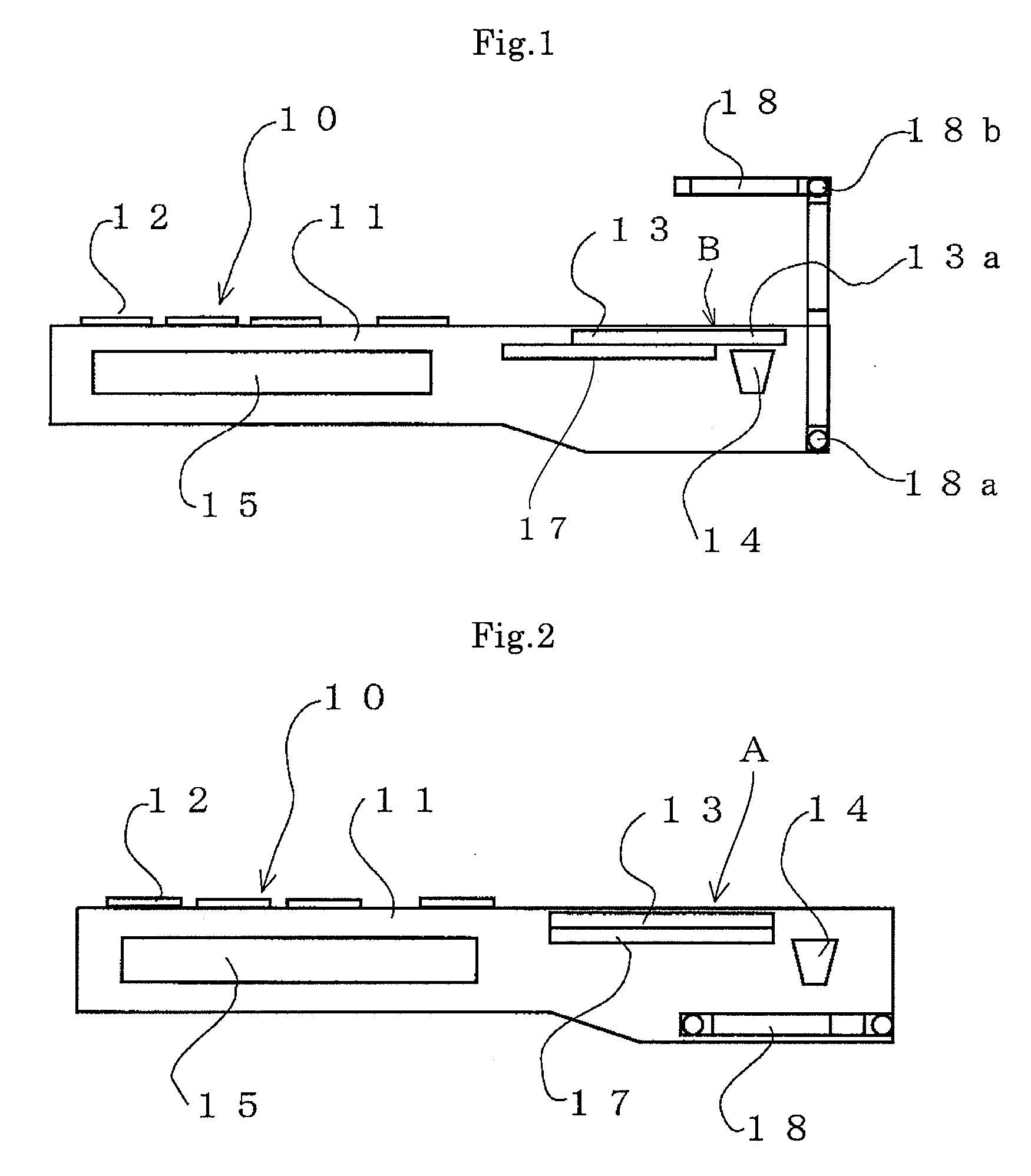
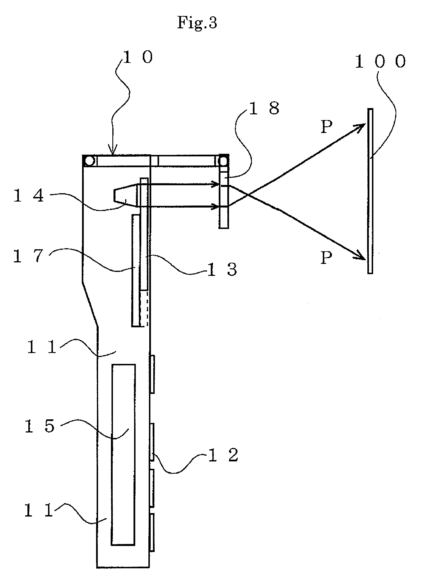
[0044]FIGS. 1 to 6 show a mobile phone 10 according to the present invention.

[0045]The mobile phone 10 has a mobile phone body 11, a keypad 12 provided on the mobile phone body 11, a transmissive liquid crystal panel 13 for information display, a backlight unit 17 using a light guide plate, an LED (light-emitting diode) device 14 as a light source for image projection, a projection lens 18, and a control unit 15.

[0046]The transmissive liquid crystal panel 13 is adapted to be slidable so as to be displaceable between an information display position A (FIG. 2) and an image projection position B (FIG. 1). When placed in the information display position A, the transmissive liquid crystal panel 13 is superimposed over the backlight unit 17. Specifically, as shown in FIG. 4, the transmissive liquid crystal panel 13 is arranged to slide within a slide window 19 provided on the front side of the mobile phone body 11.

[0047]The projection lens 18 is supported by a folding arm structure having...


PUM


Abstract

A mobile phone includes an information display device and an image projection device. The information display device has a transmissive liquid crystal panel (13) for information display that has a specific region (13a) in a part thereof. The information display device further has a backlight unit (17) that illuminates the transmissive liquid crystal panel. The image projection device has a light source (14) that illuminates the specific region (13a), and a projection lens (18) that directs light from the light source (14) received through the specific region toward a screen.

Description

[0001]This application Claims priority under 35 U.S.C. §119 to Japanese Patent Application No. JP2006-271421 filed Oct. 3, 2006, the entire content of which is hereby incorporated by reference.BACKGROUND OF THE INVENTION[0002]1. Field of the Invention[0003]The present invention relates to mobile phones and, more particularly, to a mobile phone having an image projection function.[0004]2. Description of the Related Art[0005]In recent years, portable terminal devices such as mobile phones that are equipped with an image projection device (projector) have been developed.[0006]For example, Japanese Patent Application Publication No. Hei 2-184886 discloses a portable terminal device as shown in FIG. 12. This portable terminal device has a terminal device body 61, a keypad 62, a transmissive liquid crystal panel 63 that forms an image for projection, a light source 64 for image projection, and a control unit 65. In this device, the control unit 65 is operated through the keypad 62 to form...

Claims


Application Information

Patent Timeline
Patent Type & Authority Applications(United States)
IPC IPC(8): G03B21/14G03B21/00
CPCH04N5/74G03B21/14G03B21/006G03B21/30G03B29/00
Inventor NOBA, KOUYA
Owner CITIZEN ELECTRONICS CO LTD
Learn More