Rotor for vehicular alternating current generator

a technology of alternating current generator and rotor, which is applied in the direction of dynamo-electric machines, magnetic circuit rotating parts, magnetic circuit shapes/forms/construction, etc., can solve the problems of plastic deformation on reduction of the anchorage strength between the rotary shaft and the lundell type pole core, etc., to prevent an increase in magnetic resistance, the effect of sufficient anchorage strength

Inactive Publication Date: 2008-04-03
DENSO CORP
View PDF23 Cites 19 Cited by
  • Summary
  • Abstract
  • Description
  • Claims
  • Application Information

AI Technical Summary

Benefits of technology

[0009] It is accordingly an object of the present invention to provide a rotor for a vehicular alternating current generator, which is easy to produce, can provide a sufficient anchorage strength between Lundell type pole cores, is able to prevent an increase in magnetic resistance, and is capable of suppressing the occurrence of undesired plastic deformations caused due to press-fitting operation.
[0012] With this arrangement, since the radial space width between the axial holes of the Lundell type pole cores and the rotary shaft is made larger at a first portion located adjacent to the inner end faces of the Lundell type pole cores than at the substantially press-fitted portions located on both axial outer sides of the first portion, the plastically deformed portion, as it moves downstream in the press-fitting direction along the axial hole of the upstream-side Lundell type pole core during press-fitting operation, reaches the relief space portion whereupon the plastically deformed portion is let to displace in a radial outward direction rather than further continuing the movement in the axial downstream direction. Furthermore, due to the presence of the relief space portion, there is no chance that another plastically deformed portion is newly created in the vicinity of the inner end faces of the pair of Lundell type pole cores. It is, therefore, possible to avoid the occurrence of a problem that the newly created plastically deformed portion enters between the inner end faces of the pole cores and creates an undesired axial space or gap between the inner end faces. Additionally, since the plastically deformed portion is no longer displace in the axial direction to a greater extent, it is possible to prevent undue increase in driving load on the rotary shaft and hence suppress generation of a strain deformation on the rotary shaft. Thus, the present invention is able to realize a rotor for a vehicular alternating current generator, which is easy to manufacture, can retain a sufficient anchorage strength between Lundell type pole cores, is able to prevent an increase in magnetic resistance, and is capable of suppressing the occurrence of undesired plastic deformations caused due to press-fitting operation.
[0014] Preferably, the relief space portion is formed into an annular configuration. By thus forming the relief space portion, the above-mentioned advantageous functional effects can be attained over the entire circumference of a contacting portion between the axial holes and the rotary shaft.
[0015] In one preferred form of the invention, the relief space portion is formed in a part of the axial holes. By thus forming the relief space portion on the axial hole side, it is possible to prevent reduction in torsional stiffness of the rotary shaft.
[0016] Alternatively, the relief space portion may be formed in a part of the rotary shaft. By thus forming the relief space portion on the rotary shaft side, it is possible to prevent reduction in cross sectional area of the magnetic path.
[0020] With this arrangement, since each of the relief space portions is disposed between two adjacent one of the plural knurled portions that are formed on the outer peripheral surface of the rotary shaft at the predetermined axial pitch, the relief space portions are arranged at the same predetermined axial pitch along the knurled portions of the single rotary shaft. By thus arranging the relief space portions, it is readily possible to accommodate an excess plastically deformed portion in the relief space portions, thereby facilitating easy driving of the rotary shaft into the axial holes of the pole cores.

Problems solved by technology

However, the attempted tight clamping would require a large-sized production machine and cause undesired plastic deformations on the Lundell type pole cores.
This problem may be relieved by increasing the radial cross-sectional area of the knurled groove, which may however result in a reduction in anchorage strength between the rotary shaft and the Lundell type pole cores.

Method used


Image

  • Rotor for vehicular alternating current generator
  • Rotor for vehicular alternating current generator
  • Rotor for vehicular alternating current generator

Examples


first embodiment

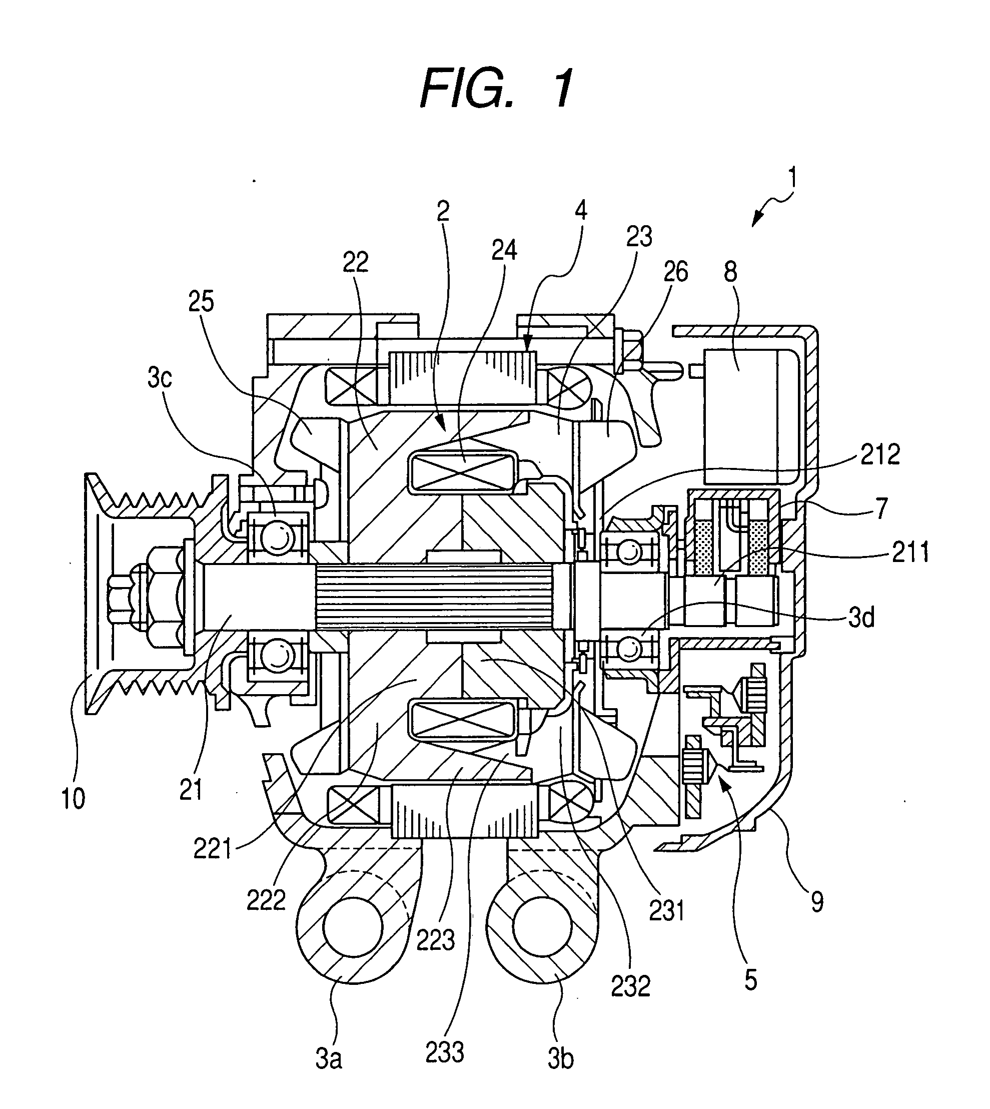
[0028] Referring now to the drawings and FIG. 1 in particular, there is shown in axial cross section a vehicular alternating current generator 1 in which a Lundell type rotor according to the present invention is incorporated.

[0029] The vehicular alternating current generator 1 includes a rotor 2 rotatably driven by an engine (not shown) via a belt (not shown) and a pulley 10, a stator 4 operating as an armature, front and rear frames 3a and 3b that support the rotor 2 and the stator 4 via a pair of bearings 3c and 3d, a rectifying device 5 connected to the stator 4 for converting alternating current output to direct current output, a brush unit 7 which holds brushes for supplying field current to a rotor coil (field coil) 24 wound on the rotor 2, a voltage control device or controller 8 for controlling an output voltage, and a protective cover 9 formed from a synthetic resin material and attached to the rear frame 3b. The protective cover 9 covers the rectifying device 5, the volta...

second embodiment

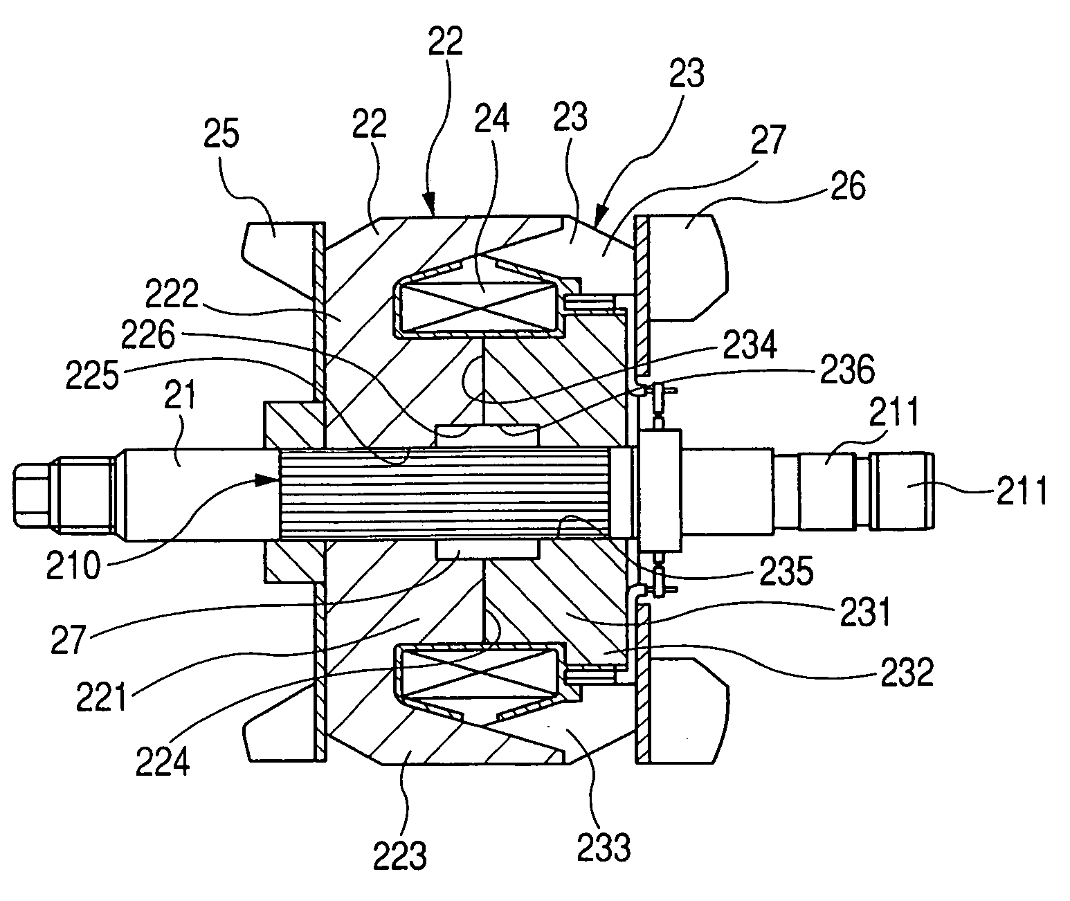
[0039] In the second embodiment shown in FIG. 1, a relief space portion 27 is defined between the large-diameter portions 226, 236 of the axial holes 225, 235 and the small-diameter portion 213 of the shaft 21. The relief space portion 27 has an annular configuration. By thus providing the small-diameter portion 213 in combination with the large-diameter portions 226, 236, it is possible to increase the volume of the relief space portion 27 without reducing the magnetic path cross-sectional area of the boss portions 221, 231.

[0040] According to modifications of the present invention, the relief space portion 27 may be formed by removing the ridges of the knurled groove 210 on the shaft 21. As an alternative, the relief space portion 27 may be formed solely by the small-diameter portion 27 of the shaft 21. In the latter case, the relief space portion 27 is formed only in a part of the shaft 21.

third embodiment

[0041]FIG. 5 shows in enlarged axial cross section a portion of a Lundell type rotor according to the present invention.

[0042] In this embodiment, the shaft 21 has a plurality of narrow relief space portions 271 to 275 formed in a portion including the knurled groove 21, at a constant pitch in the axial direction of the shaft 21. By the relief space portions 271 to 275 thus provided, the knurled groove 210 is axially divided into a plurality of knurled groove portions or segments 210A to 210F of reduced lengths.

[0043] By thus providing the relief space portions 271-275, it is possible to reduce the axial movement distance of plastically deformed portions during press-fitting operation. In addition, since the relief space portions 271-275 are distributed at regular intervals over the knurled shaft portion (knurled groove) 210, the press-fitting operation can be achieved smoothly and easily without producing a gap between the pole cores, which may lead to an increase in magnetic resi...


PUM


Abstract

A rotor for a vehicular alternating current generator has a relief space portion formed between axial holes of a pair of pole cores and a shaft for receiving therein a plastically deformed portion produced when the shaft is press-fitted in the axial holes of the pole cores. The relief space portion is located adjacent to a pair of closely contacting inner end faces of the pole cores so that the plastically deformed portion is let to move into a radially outward direction rather than further continuing movement in an axial direction within the relief space portion. The plastically deformed portion is thus prevented from entering between the inner end faces of the pole cores.

Description

CROSS REFERENCE TO RELATED APPLICATION [0001] The present application is based on and claims priority from Japanese Patent Application No. 2006-270859, filed Oct. 2, 2006, the content of which is incorporated herein by reference. BACKGROUND OF THE INVENTION [0002] 1. Field of the Invention [0003] The present invention relates generally to a rotor of a vehicular alternating current generator adapted to be installed in a motor vehicle, truck or the like, and more particularly to a fitting structure between a rotary shaft and a pair of Lundell type pole cores of the rotor. [0004] 2. Description of the Related Art [0005] Conventional rotors for vehicular alternating current generators include a pair of Lundell type pole cores each having an axial hole in which a rotary shaft is press-fitted, and a field coil wound on the pole cores. The rotors of this type will be sometimes called “Lundell type rotors”. In the Lundell type rotors, inner end faces of the pair of Lundell type pole cores a...

Claims


Application Information

Patent Timeline
Patent Type & Authority Applications(United States)
IPC IPC(8): H02K1/22
CPCH02K1/28H02K1/243
Inventor ISHIDA, HIROSHIKATO, MITSURUMCKEEHAN, CRAIG
Owner DENSO CORP
Why Eureka
Try Eureka