
Vehicular transmission

a technology of transmission and vehicle, applied in the direction of mechanical equipment, transportation and packaging, gearing, etc., can solve the problems of large engagement noise, large engagement noise, and relatively large difference in speed, so as to achieve the effect of relatively small engagement noise, and effective preventing large engagement nois

Active Publication Date: 2008-04-03
HONDA MOTOR CO LTD
View PDF9 Cites 5 Cited by
  • Summary
  • Abstract
  • Description
  • Claims
  • Application Information

AI Technical Summary

Benefits of technology

The present invention provides a vehicular transmission that includes a main shaft, countershaft, gear trains of a plurality of gear positions, and a shifter. The shifter is supported on the idle gears and is slidable along the main shafts. The shift drum includes lead grooves, in which a shift fork is engaged. The shifter can be moved between a first position and a second position to engage with different idle gears. The technical effects of this invention include improved shifting performance, reduced power loss during shifting, and improved overall transmission efficiency.

Problems solved by technology

Hei 9-317881, however, when the shifter is slidably moved to be disengaged from the one idle gear and engaged with the other idle gear, there is involved a relatively large difference in speed between the shifter and the idle gear to be engaged with therewith, resulting in a large engagement noise.
Specifically, in such a vehicle, there is produced a large engagement noise that is not operatively associated with an operation performed by an occupant of the vehicle.
This gives the occupant a sense of discomfort.

Method used


Image

  • Vehicular transmission
  • Vehicular transmission
  • Vehicular transmission

Examples


first embodiment

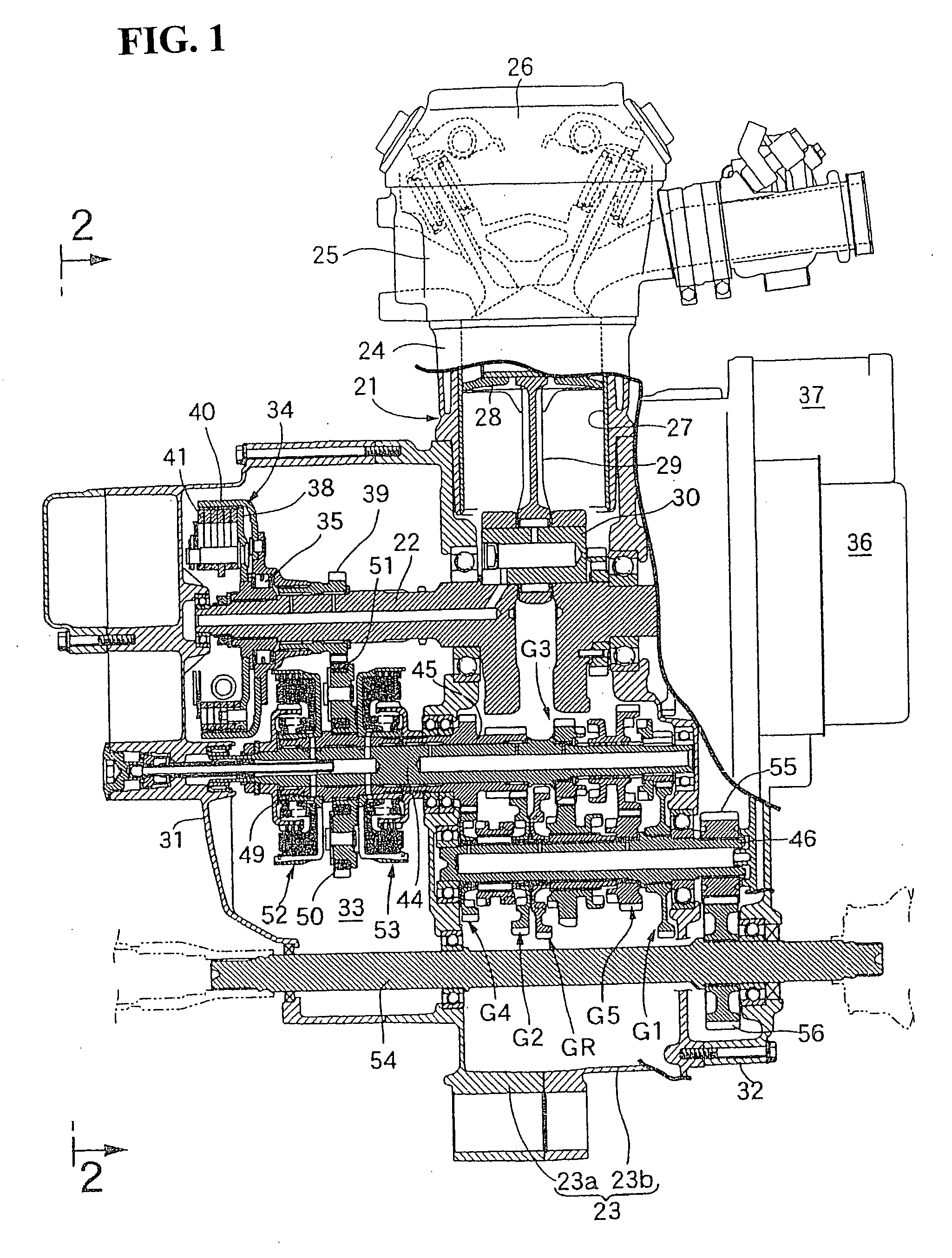
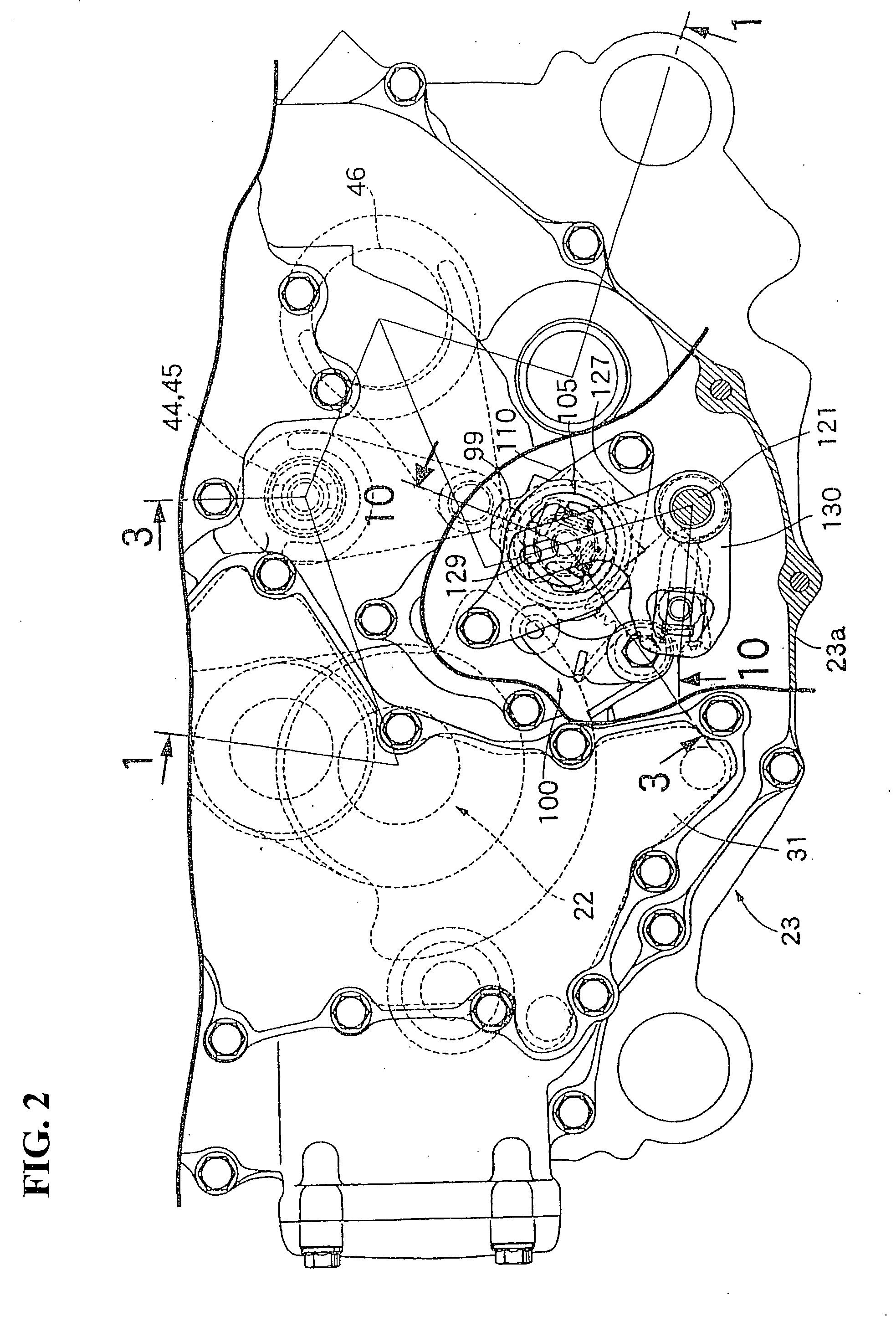
[0037]FIGS. 1-19 are views illustrating the present invention. Referring first to FIG. 1, an engine main body 21 of an engine E mounted in, for example, an off-road vehicle, includes a crankcase 23, a cylinder block 24, a cylinder head 25, and a head cover 26. Specifically, the crankcase 23 rotatably supports a crankshaft 22 having an axis extending in a vehicle width direction (parallel with a paper surface of FIG. 1). The cylinder block 24 is connected to an upper portion of the crankcase 23. The cylinder head 25 is connected to an upper portion of the cylinder block 24. The head cover 26 is connected to an upper portion of the cylinder head 25. A piston 28 slidably fitted in a cylinder bore 27 of the cylinder block 24 is linked to the crankshaft 22 via a connecting rod 29 and a crankpin 30.

[0038]The crankcase 23 includes a pair of case half bodies 23a, 23b connected together by a plane orthogonal to an axis of rotation of the crankshaft 22. First and second crankcase covers 31, 3...

second embodiment

[0105]Referring to FIG. 20 showing the present invention, of the notches SR, SN, S1-2, S2-3, S3-4, S4-5, N1, N2, and N3, the reverse positioning notch SR, the neutral positioning notch SN, the first-second speed positioning notch S1-2, the second-third speed positioning notch S2-3, the third-fourth speed positioning notch S3-4, and the fourth-fifth speed positioning notch S4-5 may each be formed into a V-shaped recess, while the neutral notches N1, N2, N3 may each be formed into an arcuate recess.

[0106]According to the second embodiment of the present invention, engagement of the drum stopper arm 100 with, and disengagement of the same from, each of the notches SR, SN, S1-2, S2-3, S3-4, and S4-5, can be made quickly and the drum stopper arm 100 can be made less easy to leave the neutral notches N1, N2, N3. The engagement state of the drum stopper arm 100 can thereby be maintained for a relatively longer period of time and the neutral state can be maintained for a relatively longer p...


PUM


Abstract

A vehicular transmission for an internal combustion engine includes lead grooves disposed on an outer periphery of a shift drum have communication portions connecting a pair of gear train establishment portions extending circumferentially along the shift drum. The communication portions include half neutral portions formed at a center thereof, extending circumferentially along the shift drum. The resulting configuration suppresses an engagement noise to a minimum during changing of a gear position through a sliding motion of a shifter.

Description

CROSS-REFERENCE TO RELATED APPLICATION[0001]The present application claims priority under 35 U.S.C. §119 to Japanese Patent Application No. 2006-270039, filed Sep. 29, 2007, the entire contents of which are hereby incorporated by reference.BACKGROUND OF THE INVENTION[0002]1. Field of the Invention[0003]The present invention relates to a vehicular transmission including a main shaft, a countershaft, gear trains, a shifter, and a shift drum. Specifically, the main shaft can receive power transmitted from an engine. The countershaft is connected to a drive wheel. The gear trains are disposed between the main shaft and the countershaft, allowing a plurality of gear positions to be selectively established. The shifter is disposed between idle gears, each forming part of two of the gear trains achieving the plurality of gear positions and supported rotatably on the main shaft or the countershaft, so as to be relatively unrotatable on, and to be slidable along, the main shaft and the count...

Claims


Application Information

Patent Timeline
Patent Type & Authority Applications(United States)
IPC IPC(8): B60K17/00
CPCF16H61/32F16H63/18Y10T74/19279Y10T74/20177Y10T74/19219
Inventor SOTANI, HIROSHIMIZUNO, KINYAHAMAOKA, SEIJIKITTAKA, EIJI
Owner HONDA MOTOR CO LTD
Learn More