Blower for a textiles processing machine

Inactive Publication Date: 2008-04-03
FALMER INVESTMENTS LTD
View PDF3 Cites 2 Cited by
  • Summary
  • Abstract
  • Description
  • Claims
  • Application Information

AI Technical Summary

Benefits of technology

[0006]Thus, the blower is provided with an air intake and an air outlet that are aligned in the same direction. This allows the overall size of the blower to be reduced compared to conventional blowers having a perpendicular intake and outlet arrangement. Also, the blower may be connected to a dyeing machine using a smaller and / or shorter pipe or tube than is required for a conventional blower. This reduced space occupancy allows a multiple tube dyeing machine to be provided with a separate and dedicated blower for each tube. Individual control of the blower speed for each tube can then be achieved. In addition, maintenance is more flexible, since failure of a blower only affects one tube. The remaining tubes in the machine can remain operational while the failed blower is repaired or replaced. Further, the need for a manifold for distributing air from one blower to a plurality of tubes is eliminated.
[0008]The outlet port may be substantially concentric with the intake port. In addition to compactness, this provided a symmetric shape for the outlet port, which allows a more even jet of air to be discharged from the blower.
[0010]The blower may comprise an outlet passage to direct air from the impeller to the outlet port. It may further comprise an intake passage to direct air from the intake port to the impeller, the outlet passage surrounding the intake passage. This configuration builds on the arrangement of the outlet port surrounding the inlet port, and offers a highly compact design for the blower.
[0011]At least part of the outlet passage may have a spiral shape with a longitudinal axis substantially parallel to the direction in which air is discharged. This improves the distribution and rate of air discharge through the outlet port. A spiral shape gives a longer outlet passage within the same overall length of the blower, and a longer passage offers more scope for controlling the air flow along the passage through engineering of the outlet passage shape and dimensions.
[0012]Also, at least part of the outlet passage is divided into two or more sub-passages extending side by side. Again, this enhances the evenness of the air discharge, and offers greater scope for manipulating the width of the outlet passage to modify the air flow.
[0013]For example, the outlet passage may increase in cross-sectional area between the impeller and the outlet port. By Bernoulli's law, an increase in area in a flow channel decreases the kinetic energy of the flowing fluid, in this case air, and increases the pressure. Thus, the jet of air discharged by the blower is more forceful and better able to loosen fabric in a textiles machine.

Problems solved by technology

Blowers of this type are often installed by the side of the associated dyeing machine, and the combined blower and machine can occupy a large amount of space.
This impacts on the design of dyeing machines, since the large size makes it undesirable to provide a separate blower for each type in a multiple tube loading dyeing machine.
It is difficult to achieve an even distribution of air flow among the tubes, so that each tube may experience a different force in the air jet, resulting in uneven dyeing.

Method used


Image

  • Blower for a textiles processing machine
  • Blower for a textiles processing machine
  • Blower for a textiles processing machine

Examples


Embodiment Construction

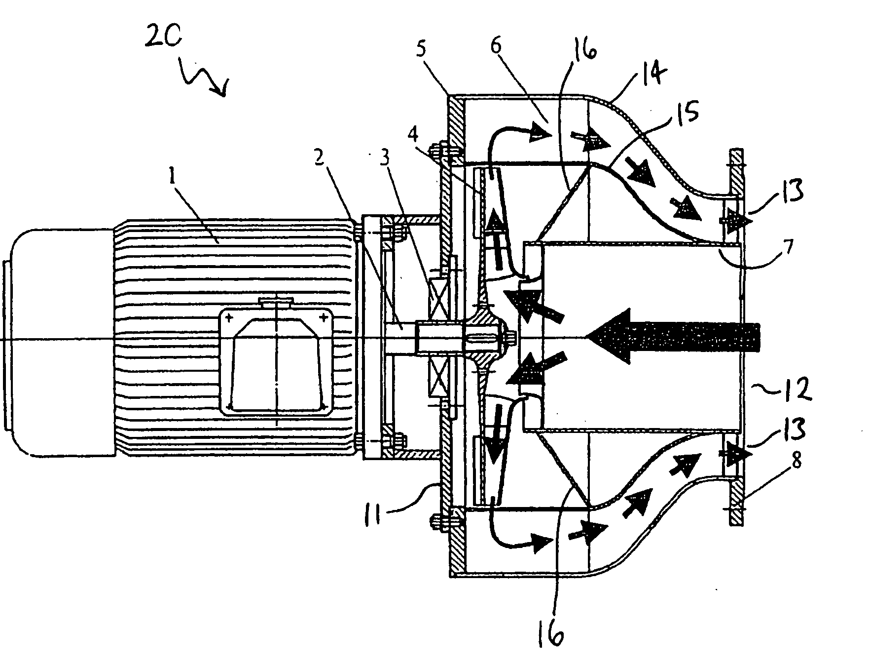
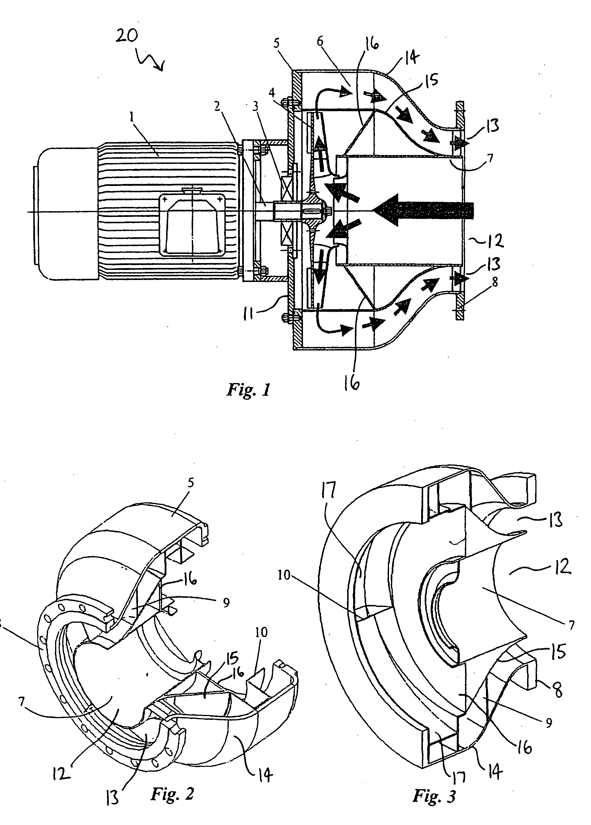
[0023]FIG. 1 shows a cross-sectional view of an embodiment of a blower according to the present invention. The blower 20 comprises two main parts: an impeller, and a housing defining an air intake and an air outlet. The impeller 4 may be any conventional impeller used for air blowers and fans. It is substantially dish-shaped and has a plurality of impeller blades extending radially from a central hub. The hub of the impeller 4 is mounted on a drive shaft 2 of a driving motor 1, by which the impeller can be rotated in the conventional manner.

[0024]Fitted over the impeller 4 is a housing 5, which is mounted to the driving motor 1 by a rear plate 11, through which the drive shaft 2 extends. The housing 5 is circular in cross-section (in a plane orthogonal to the rotational axis of the impeller 4) and is positioned concentrically with the impeller 4 and the drive shaft 2. A mechanical seal 3 is disposed between the rear plate 11 and the drive shaft 2, to isolate the housing 5 from vibra...


PUM


Abstract

A blower for use with a textiles processing machine such as a dyeing machine including an intake port and an outlet port each in communication with an impeller that draws air in through the intake port and discharges air through the outlet port, the intake port and the outlet port being arranged such that air is drawn in in a direction opposite to but substantially parallel to a direction in which air is discharged.

Description

BACKGROUND OF THE INVENTION[0001]The present invention relates to a blower, particularly but not exclusively for use with a textiles processing machine.[0002]Jets of air can be applied to textiles during a fabric dyeing process, such as piece dying. A jet of air is directed onto fabric in a piece dying machine to loosen the fabric, giving a more even dyeing effect. The jet is delivered by a nozzle connected to a blower. The blower has an air intake (suction) and an air outlet (discharge); these are conventionally arranged along perpendicular directions. An example of such a blower is given in WO 95 / 08662.[0003]Blowers of this type are often installed by the side of the associated dyeing machine, and the combined blower and machine can occupy a large amount of space. This impacts on the design of dyeing machines, since the large size makes it undesirable to provide a separate blower for each type in a multiple tube loading dyeing machine. Thus, two or more tubes share a blower. This ...

Claims


Application Information

Patent Timeline
IPC IPC(8): D06B3/28F03B3/00
CPCD06B3/28F04D29/4253D06B23/00D06B3/00
Inventor TSUI, WILLIAM TAK MING
Owner FALMER INVESTMENTS LTD
Why Eureka
Try Eureka