
Valve drive for an internal combustion engine

A drive, internal combustion engine technology, applied in the direction of non-mechanical actuated valves, machines/engines, valve devices, etc., can solve problems such as cost-intensive, infeasible, and complex three-level systems

Inactive Publication Date: 2019-11-22
MAHLE INT GMBH
View PDF6 Cites 0 Cited by
  • Summary
  • Abstract
  • Description
  • Claims
  • Application Information

AI Technical Summary

Problems solved by technology

Due to this, the use of zero-lift wheels, via which eg a cylinder can be switched off, is limited by the
Alternatively, a three-stage system capable of switching between firing, braking and shut-off modes is obviously also conceivable, but three-stage systems are complex, critical in terms of installation space, and cost-intensive
Cylinder shutoff with zero-lift wheels is generally not feasible with so-called axially adjustable cam followers (shift rollers)

Method used


Image

  • Valve drive for an internal combustion engine
  • Valve drive for an internal combustion engine
  • Valve drive for an internal combustion engine

Examples


Embodiment Construction

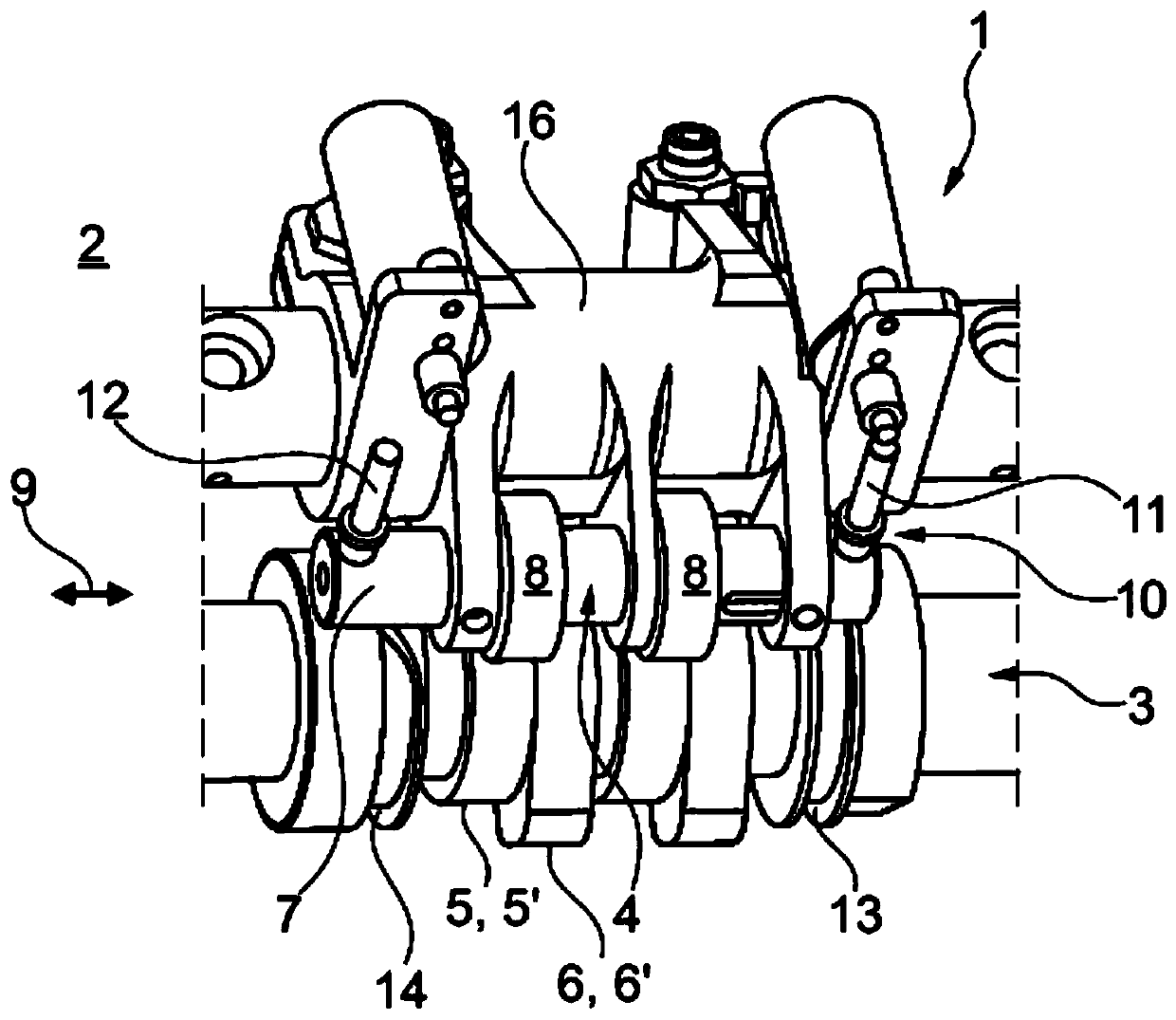
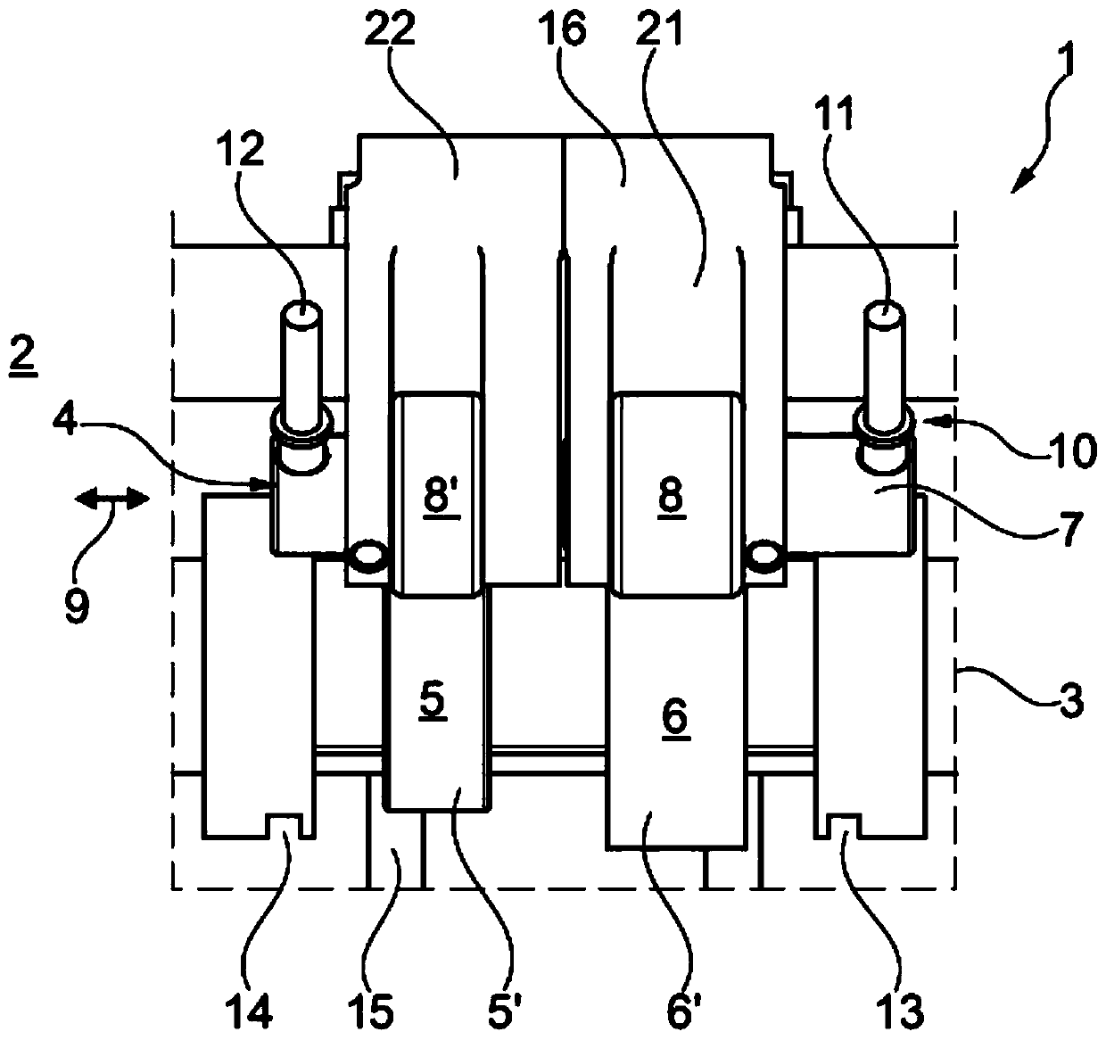
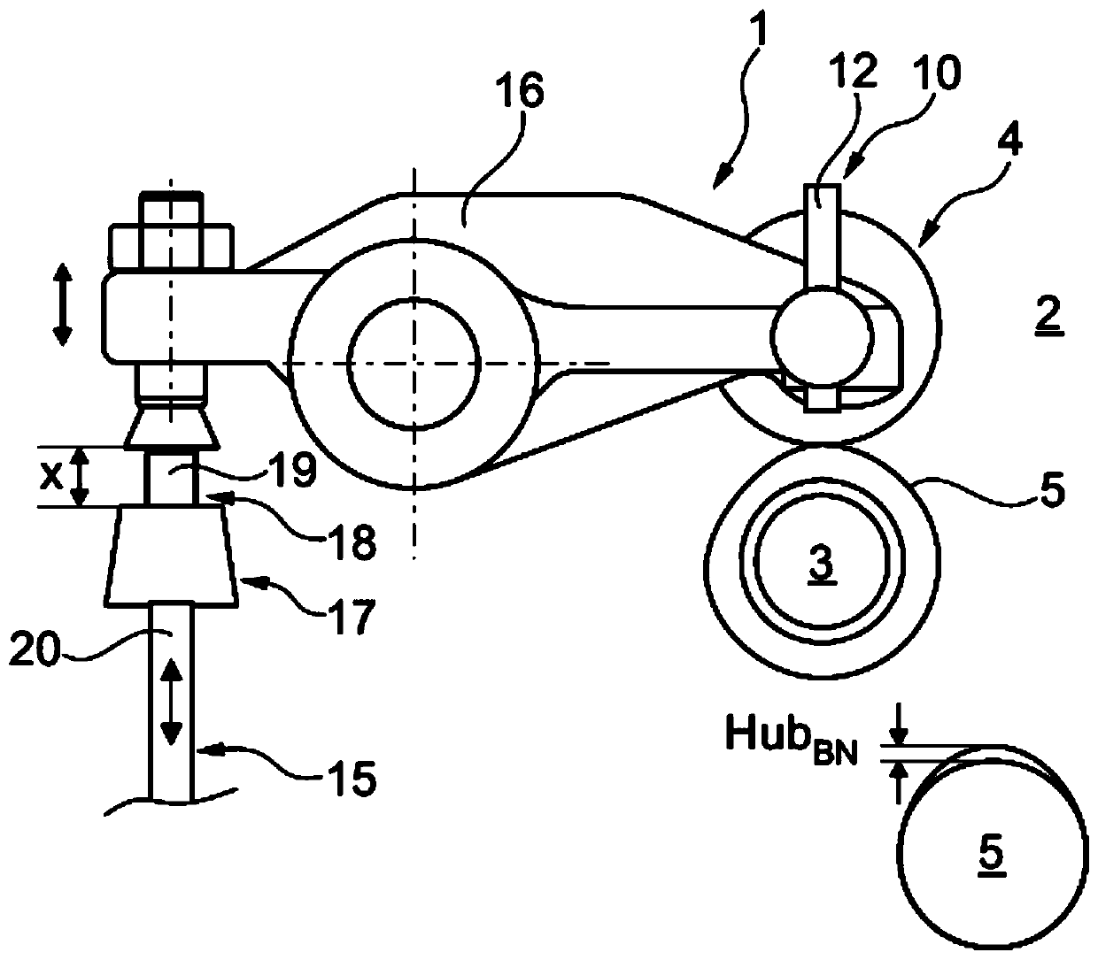
[0024] according to Figure 1 to Figure 6 , the valve drive 1 according to the invention comprises a camshaft 3 of an internal combustion engine 2 , the internal combustion engine 2 having at least one cam follower 4 not otherwise shown in more detail. The camshaft 3 comprises: at least one first cam 5 fixed non-rotatably on the camshaft 3 ; and a second cam 6 arranged axially adjacent to the first cam 5 . Here, in a first position, the cam follower 4 is drivingly connected to the first cam 5, and in a second position, is drivingly connected to the second cam 6, wherein, according to figure 1 , the cam follower 4 is in its first position, due to which it is connected to the first cam 5 . according to figure 1, each roller 8 is rotatably mounted on a roller pin 7 which is adjustable in the axial direction 9 . The valve drive 1 additionally comprises an adjustment device 10 having a first adjustable dowel 11 and a second adjustable dowel 12 which are arranged spaced apart fro...


PUM


Abstract

The invention relates to valve drive (1) for an internal combustion engine (2). The valve drive (1) may include a camshaft (3), at least one cam follower (4), wherein the camshaft (3) comprises at least one first cam (5), which is fixedly arranged on the camshaft (3) and a second cam (6), which is adjacent to the first cam (5) in the axial direction. The second cam (6) is designed to be an exhaustcam (6'), and the first cam (5) is designed to be a braking cam (5'). Compared with the second cam (6), the first cam (5) has a reduced cam lift. The cam follower (4) is connected to an exhaust valve(15) through a rocking bar (16). A hydraulically actuated element (18) is arranged on the rocking bar (16) or the valve bridge (17) of the exhaust valve (15). The hydraulically actuated element (18)is adjustable between two positions. On the first position, the hydraulically actuated element (18) is operably connected to the braking cam (5'), and on the second position, the hydraulically actuated element (18) is separated from the braking cam (5') so as to shut down the cylinder.

Description

technical field [0001] The invention relates to a valve drive for an internal combustion engine according to the preamble of claim 1 , which has a camshaft and has at least one cam follower. The invention additionally relates to an internal combustion engine having such a valve drive. Background technique [0002] A universal valve drive for an internal combustion engine is known which has a camshaft and has at least one cam follower and a first cam which is non-rotatably arranged on the camshaft and a second cam which is arranged as Axially adjacent to the first cam. Here, the cam follower drives a first cam connected to the corresponding cam set in a first position and a second cam connected to the corresponding cam set in a second position. [0003] The adjusting device of the valve drive has a first adjustable stud and a second adjustable stud, in each case the adjusting device of the valve drive interacts with a slotted guide rail arranged on the camshaft. By means o...

Claims


Application Information

Patent Timeline
Patent Type & Authority Applications(China)
IPC IPC(8): F01L13/00F01L13/06F01L9/02F01L1/18F01L1/047F01L9/10F01L9/11
CPCF01L13/0036F01L13/06F01L1/18F01L1/047F01L13/0005F01L2013/0078F01L2001/0473F01L2013/001F01L9/10F01L13/065F01L2013/105F01L1/2411F01L1/267F01L1/053F01L2305/00F01L13/0015F01L2001/054F01L2305/02F01L9/11
Inventor 帕特里克·奥尔瑟托尔斯腾·伊内
Owner MAHLE INT GMBH
Learn More