Eyeglasses

Pending Publication Date: 2022-03-31
KAUFMANN SANDRA +1
View PDF0 Cites 0 Cited by
  • Summary
  • Abstract
  • Description
  • Claims
  • Application Information

AI Technical Summary

Benefits of technology

The present invention provides eyeglasses with a compact design when closed and can fit into a protective shell or case. The design also prevents the eyeglasses from being crushed in the closed position.

Problems solved by technology

As a result, the displays are only suitable for small presentations of information, such as text, i.e., reading matter, pictures or videos.
This has the effect that many people have difficulties to read the information, in particular text information, even if their visual performance is sufficient for everyday life.
However, the separate carrying of a visual aid, such as eyeglasses, solely for reading information from the small display of an electronic handheld device is cumbersome.
Such eyeglasses easily get lost or cannot be found within a reasonable time as people cannot recall where they did drop or pouch the visual aid the last time.
However, this requires that the eyeglasses in a closing position of the temples are quite compact.
However, the eyeglasses are not sufficiently compact in the closing position for being able to be inserted into a protective shell or protective case of an electronic handheld device.
Moreover, the pivot joint mechanism with several pivot axis is quite complex and thus expensive in production.

Method used


Image

  • Eyeglasses
  • Eyeglasses
  • Eyeglasses

Examples


first embodiment

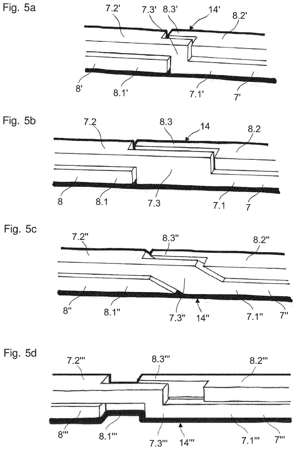
[0148] the crossing portions 7.4, 8.4 of the temples 7, 8, as viewed from the back or front side in the closing position, have a rectangular basic shape with a height which corresponds to the sum of the heights of the first and second longitudinal component (portion) 7.1, 7.2; 8.1, 8.2 (see FIG. 5b). Due to this, the pairing of crossed first and second temples 7, 8 in the closing position has a constant, i.e., uniform height and in particular a straight upper and lower edge.

[0149]The crossing portions 7.4, 8.4 of the temples 7, 8 have a width which is half of the width of the first longitudinal component (portion) 7.1, 8.1, respectively the second longitudinal component (portion) 7.2, 8.2. Due to this, the pairing of crossed first and second temples 7, 8 in the closing position has a constant, i.e., uniform width.

[0150]All in all the pairing of crossed first and second temples 7, 8 in the crossed closing position forms a cuboid structure with a constant, i.e., uniform height and a c...

second embodiment

[0151] the crossing portions 57.4, 58.4 of the temples 57, 58, as viewed from the back or front side in the crossed closing position, have a curved course with a diagonal intersection which connects with the first, straight lower longitudinal portion 57.1, 58.1 and with the second straight upper longitudinal portion 57.2, 58.2. In present embodiment the crossing portions 57.3, 58.3 have the same height as the first and second longitudinal portion 57.1, 57.2; 58.1, 58.2.

[0152]The displacement in height of the second longitudinal portion 57.2, 58.2 relative to the first longitudinal portion 57.1, 58.1 established by the crossing portions 57.3, 58.3 is shown in FIG. 11 by means of a change in the hachures. In other words, the hachures of the upper lying second longitudinal portion 57.2, 58.2 is more wide-meshed than the hachures of the underlying first longitudinal portion 57.1, 58.1 of the same type of hachures.

[0153]The second longitudinal portions 57.2, 58.2 have a width that is sma...


PUM


Abstract

An eyeglass frame with an eyeglass front for receiving at least one eyeglass lens, and with a left and right temple, which are pivotably connected to the eyeglass front via a pivot joint connection for holding the eyeglass frame on the head of an eyeglass wearer, wherein the eyeglass front forms at least an upper frame section, wherein the temples can be pivoted relative to the eyeglass front from a position of use into a closing position, in which the temples are arranged above the upper frame section, and vice versa. The temples are arranged in a crossed position relative to each other in their closing position above the upper frame section.

Description

BACKGROUND OF THE INVENTIONField of the Invention[0001]The invention lies in the technical field of visual aids and concerns an eyeglass frame as well as eyeglasses, including an eyeglass frame according to the invention. Furthermore, the invention also concerns the use of the eyeglasses according to the invention and a set including a protective shell or casing for an electronic handheld device and eyeglasses according to the invention.Description of Related Art[0002]Electronic handheld devices for displaying information, such as smartphones, cellular phones, tablets or e-book readers are highly popular. Such devices make it possible to procure or retrieve information, such as news, notifications, e-mails, timetables or in general reading matter, pictures and videos, virtually location-independent and in particular whilst travelling.[0003]Such electronic handheld devices are characterised by relatively small displays. As a result, the displays are only suitable for small presentati...

Claims


Application Information

Patent Timeline
IPC IPC(8): G02C5/00G02C5/20
CPCG02C5/006G02C5/20G02C5/14A45C2011/002A45C11/04A45F2200/0541
Inventor KAUFMANN, SANDRAFINK, MONIKAHATTLER, ERIC
Owner KAUFMANN SANDRA
Why Eureka
Try Eureka