Tool head for a rotating tool

a tool head and tool head technology, applied in the field of expandable tool head for rotating tools, can solve the problems of a large number of individual components of the device and is comparatively complicated to manufacture, and achieve the effect of convenient mounting and precise fine adjustment of the radial expansion

Active Publication Date: 2014-08-26
KENNAMETAL INC
View PDF16 Cites 0 Cited by
  • Summary
  • Abstract
  • Description
  • Claims
  • Application Information

AI Technical Summary

Benefits of technology

[0004]The object of the present invention is to specify a tool head of the type initially mentioned, which has as few components as possible, is simple to manufacture and allows an especially precise fine adjustment of the radial widening. Furthermore, the adjusting device provided for this purpose in the tool head should require as little installation space as possible, so that the tool head can, as required, have a highly compact design.
[0009]According to the fundamental operating principle of a differential screw of this kind, a differential mechanism, as it is known, is therefore implemented, in which the resulting axial stroke of the adjusting sleeve is always lower than the axial stroke of the adjusting screw when the latter is screwed into the threaded bore of the basic body. Since the resulting axial stroke of the adjusting sleeve depends on the difference between the leads of the two thread regions, in the extreme case of a very small lead difference, the stroke of the adjusting sleeve brought about during a rotation of the adjusting screw can be kept very low. Owing to the thread step-up, an especially precise fine adjustment of the axial position of the adjusting sleeve becomes possible independently of the conical geometry of the outer face of the adjusting sleeve, thus giving rise in a way known per se to the desired spreading or expansion of the tool head in the radial direction as a result of the wedge effect of the adjusting sleeve. In other words, in the present invention, in addition to the known wedge-type mechanism a further mechanism which extends and improves the setting possibilities is also implemented by the differential screw.
[0010]In a second variant, the two threaded portions of the adjusting screw have different flight directions. That is to say, one threaded portion is left-handed and the other right-handed. The associated internal threads of the receptacle in the basic body of the tool and in the adjusting sleeve are, of course, adapted to this configuration. Since, in this variant, the effective stroke travel of the adjusting sleeve in the axial direction depends on the sum of the leads of the two thread regions, a correspondingly high step-up can be provided, so that, by means of relatively small rotational movements on the adjusting screw, a relatively high force component can be introduced into the annular portion of the tool head via the adjusting sleeve acting as a spreading cone.
[0011]In both instances, the differential screw also makes it possible to release the adjusting device easily. Indeed, when the annular portion is being spread open, the actuating sleeve is usually braced markedly in the receptacle, that is to say in the annular portion, due to the high force introduced. However, when the differential screw is rotated counter to the tensioning direction, it is easily released from this state of tension, since, as a result of the step-up ratio, it then also moves the adjusting sleeve out of the receptacle again.
[0014]In an especially advantageous refinement, the adjusting screw and the adjusting sleeve are arranged, countersunk completely, in the cavity surrounded by the annular portion of the basic body, that is to say do not project with respect to the annular portion in the region of the end face of the tool head. Blind holes and steps in a workpiece can consequently be machined without difficulty.
[0021]The advantages achieved by means of the invention are, in particular, that the use of a differential screw as part of an adjusting device with a conical adjusting sleeve allows an especially precise fine adjustment of the radial expansion of an expandable tool head. By the adjusting sleeve being used, no frictional forces are transmitted to the annular portion of the tool head during bracing. To be precise, as soon as the adjusting sleeve comes to bear, flush, in the surrounding receptacle, that is to say in the annular portion, and has been braced, said adjusting sleeve does not rotate any further, but, instead, when the adjusting screw penetrates further, is displaced only in the axial direction and at the same time, as a result of its conical outer contour, expands the tool head. As compared with solutions known hitherto, the tool head according to the invention manages with fewer parts and can be mounted more easily.

Problems solved by technology

The adjusting device therefore has a relatively large number of individual components and is comparatively complicated to manufacture.

Method used


Image

  • Tool head for a rotating tool
  • Tool head for a rotating tool

Examples


Embodiment Construction

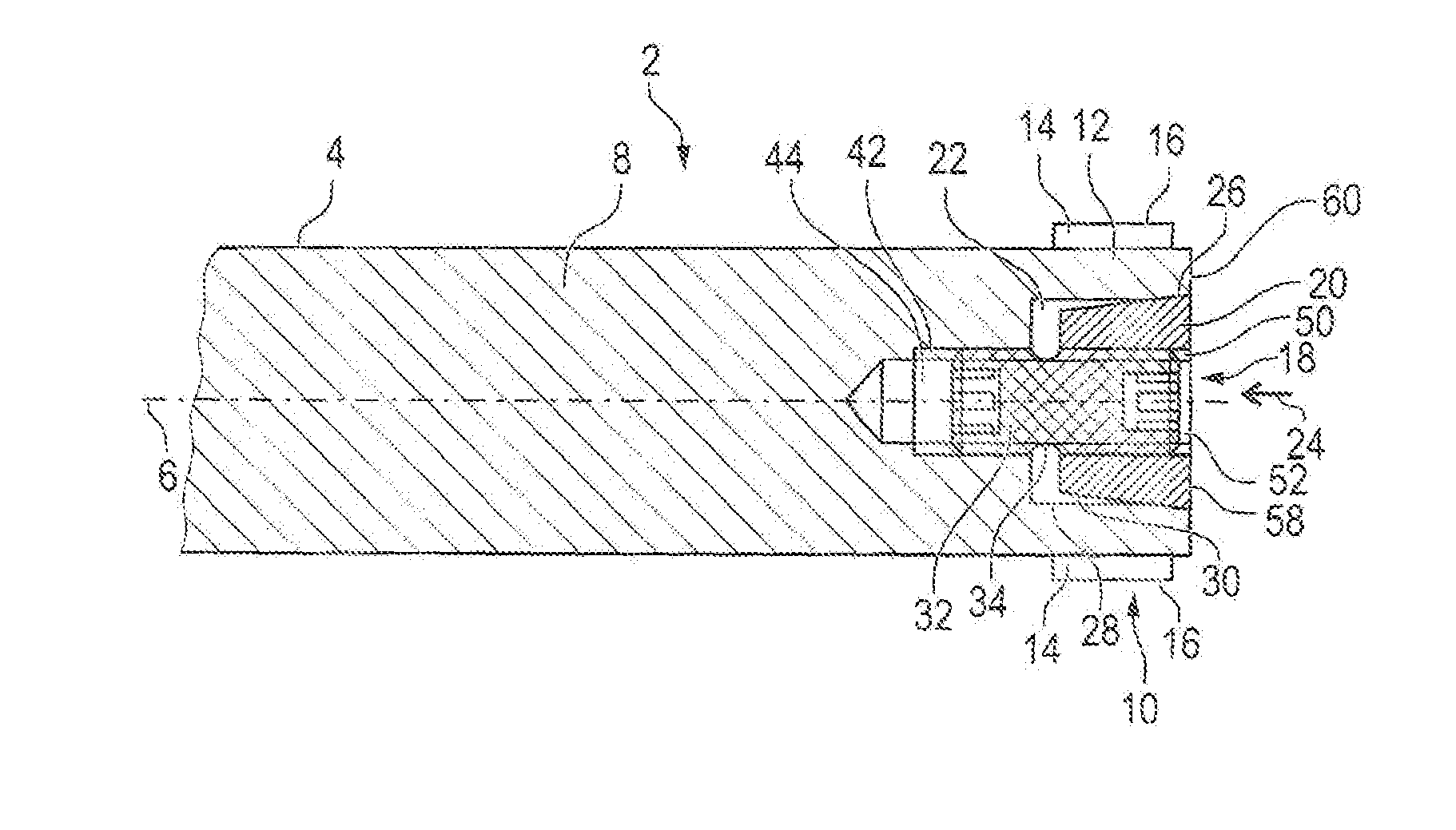
[0027]The tool 2, the detail of which is illustrated in longitudinal section in FIG. 1, is a reamer for the fine machining of bores, in particular in metal parts. However, it could also be a milling tool or another kind of combination tool. The tool 2 comprises an elongate tool shank 4 with a basic body 8 designed essentially radially symmetrically with respect to a mid-axis 6, and also a tool head 10 provided on the end face (here on the right) on the tool shank 4. The tool head 10 has an annular portion 12 which is integrally formed onto the basic body 8 and on the outsides of which a number of cutting elements 14 are attached or integrally formed in a known way (indicated merely diagrammatically here). Furthermore, depressions may be provided on the outside of the basic body 8, which act as chip spaces for transporting away chips occurring during the machining of workpieces. At the left end, not illustrated here, the tool shank 4 may be coupled to a machine tool which sets the to...


PUM

PropertyMeasurementUnit
forceaaaaaaaaaa
tensionaaaaaaaaaa
radiusaaaaaaaaaa

Abstract

A tool head (10) for a rotating tool (2) includes a basic body (8), an annular portion (12) arranged on an end face on the basic body (8) and surrounds a cavity (22), and an adjusting device (18) including an adjusting screw (32) with a shank (34) and an adjusting sleeve (20). The shank (34) having a first shank portion (36) engaging a threaded bore (44) in the basic body (8). The adjusting sleeve (20) is displaceable by the adjusting screw (32) and has a conical outer face (30) that interacts with an inner face (28) of the annular portion (12) in such a way that, when the adjusting screw (32) is being screwed into the threaded bore (44), the annular portion (12) is spread open by the adjusting sleeve (20).

Description

FIELD OF THE INVENTION[0001]The invention relates to an expandable tool head for a rotating tool, in particular a reamer, milling tool or other kind of combination tool. One or more can be attached, for example glued, soldered or clamped, as desired, to the tool head. By means of an adjusting device integrated into the tool head, the tool head can be widened or expanded, with the result that the radial position of the cutting bodies can be set. Consequently, on the one hand, the basic position of the cutting bodies can be fixed in the manner of fine adjustment and, on the other hand, readjustment for wear compensation is possible.BACKGROUND OF THE INVENTION[0002]A tool head of the above-mentioned type for use in a reamer is known, for example, from international laid-open publication WO 2008 / 155104 A1. The adjusting device provided there comprises a conical adjusting sleeve which surrounds an adjusting screw in the manner of a floating mounting and the outer face of which interacts ...

Claims


Application Information

Patent Timeline
Patent Type & Authority Patents(United States)
IPC IPC(8): B23D77/10
CPCB23D77/10Y10T408/858Y10T408/85843Y10T408/85892
Inventor ZIMMERMAN, ARMIN JOSEFSPICHTINGER, XAVERECKL, BERNHARDMANNER, HEINRICH GEORG
Owner KENNAMETAL INC
Why Eureka
Try Eureka