
Close-coupled catalytic converter

a catalytic converter and closed-coupling technology, applied in the direction of physical/chemical process catalysts, separation processes, lighting and heating apparatus, etc., can solve the problems of difficult to dispose of front catalysts near engines, high manufacturing process, and high manufacturing cost of canning, so as to improve the efficiency of the catalytic converter, simplify the structure of the catalyst shell and the structure for the configuration of the oxygen sensor, and enhance the effect of configuration performan

Inactive Publication Date: 2008-04-03
HYUNDAI MOTOR CO LTD
View PDF6 Cites 12 Cited by
  • Summary
  • Abstract
  • Description
  • Claims
  • Application Information

AI Technical Summary

Benefits of technology

[0016]The present invention has been made in an effort to provide a close-coupled catalytic converter having the advantages that a structure of a shell for a catalyst and a structure for configuration of an oxygen sensor are simplified so that configuration performance is enhanced, and a rate of coating of a front catalyst is optimized so that efficiency of the catalytic converter is enhanced and manufacturing cost is reduced.
[0017]Also the present invention has been made in an effort to provide a close-coupled catalytic converter having the advantages that a front catalyst is closely disposed near an engine so that the light-off characteristic is improved, a coating ratio of a front catalyst is optimized, and efficiency of a cross-section of a rear catalyst is improved so that efficiency of a CCC catalytic converter is improved.
[0023]The front catalyst may be disposed near to the front muffler pipe at a second predetermined length in order to reduce a time to reach a temperature of activating the catalyst.

Problems solved by technology

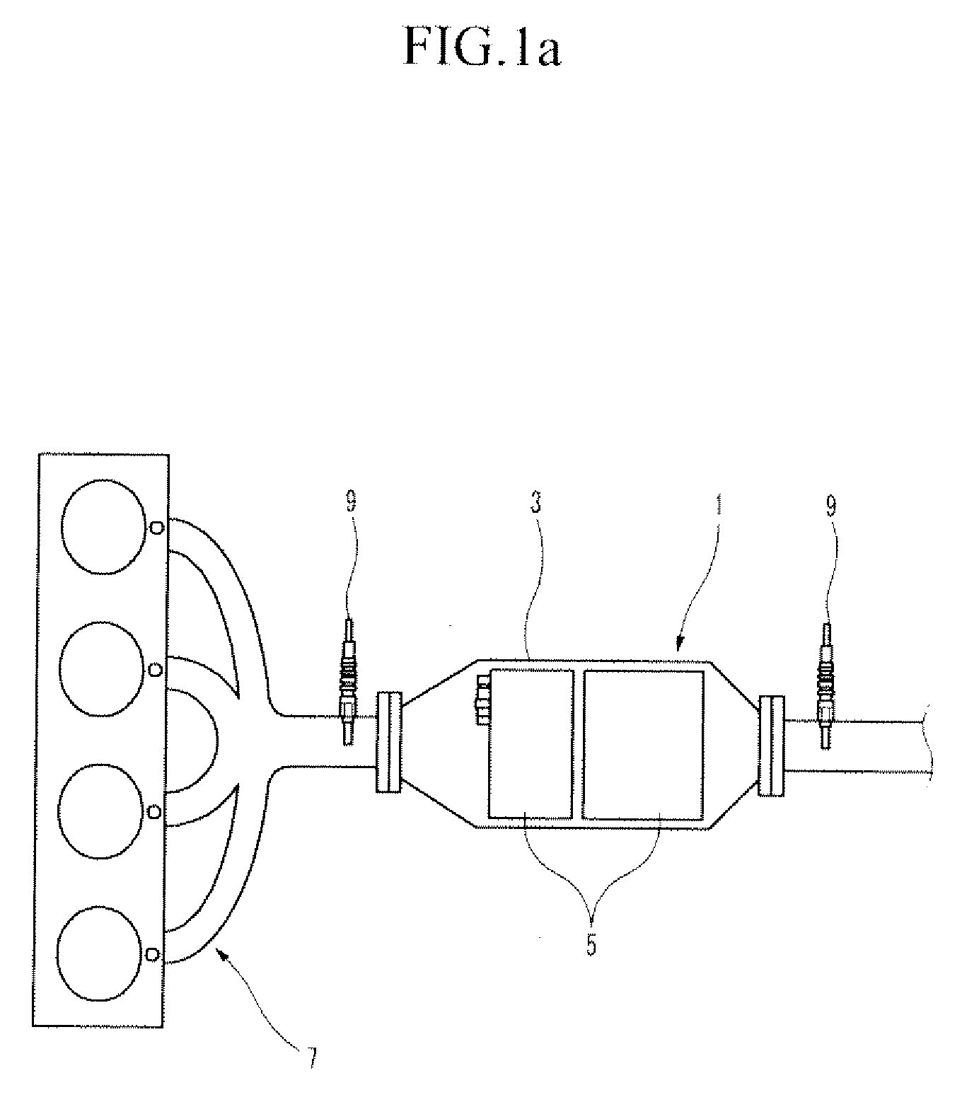
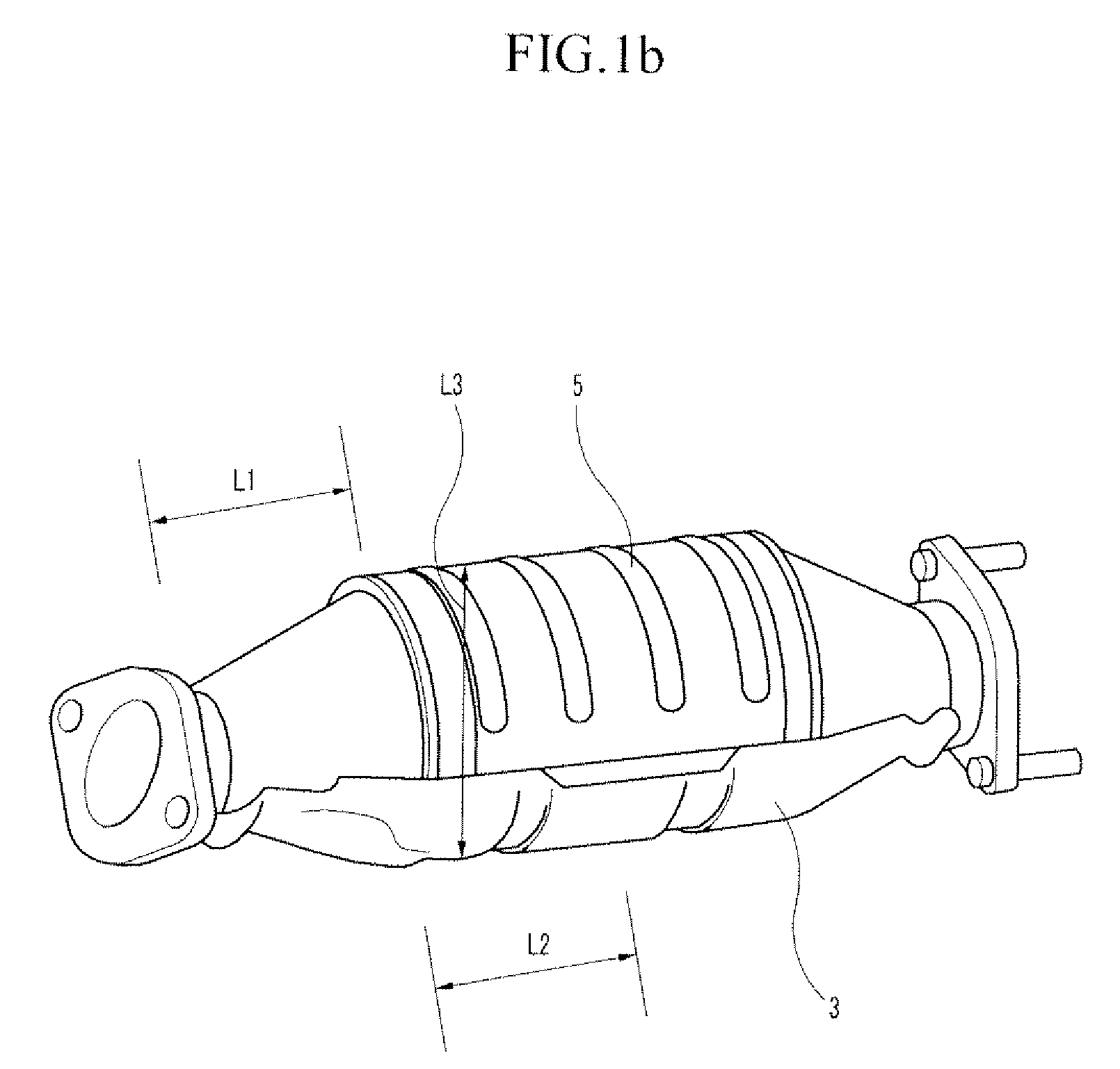
However, this conventional catalytic converter requires a plurality of cones and shells so that a manufacturing cost of canning is high, and also requires a plurality of welding processes so that the manufacturing process is increased.
Because of a size of a diameter of a front shell, an assembly tool may often interfere with the shell during assembly of the shell to an exhaust manifold, a pipe, and so on.
However, it is difficult to dispose the front catalyst near an engine because of the above-mentioned interference.

Method used


Image

  • Close-coupled catalytic converter
  • Close-coupled catalytic converter
  • Close-coupled catalytic converter

Examples


Embodiment Construction

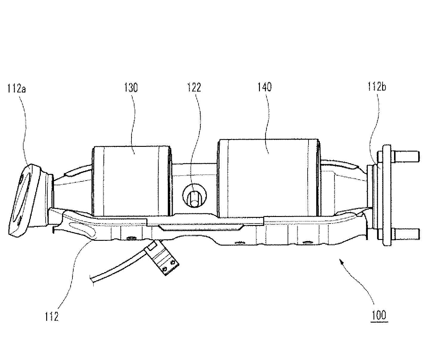
[0041]Hereinafter reference will now be made in detail to various embodiments of the present invention, examples of which are illustrated in the accompanying drawings and described below. While the invention will be described in conjunction with exemplary embodiments, it will be understood that present description is not intended to limit the invention to those exemplary embodiments. On the contrary, the invention is intended to cover not only the exemplary embodiments, but also various alternatives, modifications, equivalents and other embodiments, which may be included within the spirit and scope of the invention as defined by the appended claims.

[0042]FIG. 3 is schematic diagram of a CCC catalytic converter according to an exemplary embodiment of the present invention. FIG. 4 is a perspective view of the CCC catalytic converter according to an exemplary embodiment of the present invention, and FIG. 5 is an internal perspective view of the CCC catalytic converter according to an e...


PUM

PropertyMeasurementUnit
lengthaaaaaaaaaa
lengthaaaaaaaaaa
lengthaaaaaaaaaa

Abstract

A close-coupled catalytic converter according to an exemplary embodiment of the present invention includes: a front catalyst and a rear catalyst that are cylindrically shaped, coated with a metal catalyst, and disposed separately from each other; and a catalyst cover including an upper shell and a lower shell, and the upper and lower shells are semi-cylindrically shaped, wherein an end of the catalyst cover is connected with a front muffler pipe that is connected with an exhaust manifold and the other end of the catalyst cover is connected with a rear muffler pipe that emits an exhaust gas. The structures of a shell for a catalyst and for configuration of an oxygen sensor are simplified so that manufacturing process and cost are reduced and purifying performance is enhanced. Since back pressure is reduced, engine performance is enhanced.

Description

CROSS-REFERENCE TO RELATED APPLICATION[0001]This application claims priority to and the benefit of Korean Patent Application No. 10-2006-0097328 filed in the Korean Intellectual Property Office on Oct. 02, 2006, the entire contents of which are incorporated herein by reference.BACKGROUND OF THE INVENTION[0002](a) Field of the Invention[0003]The present invention relates to a close-coupled catalytic converter. More particularly, the present invention relates to a close-coupled catalytic converter in which a structure of a shell for a catalyst and a structure for configuration of an oxygen sensor are simplified so that configuration performance is enhanced, and a rate of coating of a front catalyst is optimized so that efficiency of the catalytic converter is enhanced and manufacturing cost is reduced.[0004](b) Description of the Related Art[0005]A catalytic converter (or a catalyst converter) is a device that converts carbon monoxide, hydrocarbon, nitrous oxide, and so on, contained ...

Claims


Application Information

Patent Timeline
Patent Type & Authority Applications(United States)
IPC IPC(8): F01N3/10
CPCF01N13/008F01N13/02F01N13/0097F01N2260/20F01N13/1805B01J23/38
Inventor KIM, SANGBEOMKIM, SUNGKUN
Owner HYUNDAI MOTOR CO LTD
Learn More