Method for loading and unloading of a machine tool with tools

a machine tool and tool technology, applied in the direction of metal-working holders, supporters, positioning apparatus, etc., can solve the problems of unsuitable matrix magazine devices, unacceptably high transfer times, and inability to execute the crossing from the vertical into the horizontal path, so as to reduce the time of tool changing and the effect of dead times

Inactive Publication Date: 2008-03-20
MUSER JOSEF +1
View PDF1 Cites 9 Cited by
  • Summary
  • Abstract
  • Description
  • Claims
  • Application Information

AI Technical Summary

Benefits of technology

[0012] The movement of the gripper device of the manipulation device runs along continuously curved paths during the tool change, by which abrupt velocity changes are avoided. The manipulation device therefore does not have to be abruptly braked or accelerated during the tool change. Dead times may thus be avoided and the tool changing times may be reduced.

Problems solved by technology

Using the disclosed apparatus, it is not possible to execute the crossing from the vertical into the horizontal path as a curve.
Furthermore, the device known from CH 531 391 A5 is not suitable at all for use in a matrix magazine, because the insertion may only be implemented from one side.
If such a gripper unit was used in a matrix magazine, the space required would increase by approximately 10 times, which would result in unacceptably high transfer times.
However, the tools are situated relatively far from one another on a surface in a matrix magazine (because of the large number), so that such a robot must have relatively long levers.
These levers would result in a very large space requirement.
The controller of such robots is also more complicated than that of robots having two linear axes.
This braking and acceleration procedure has the disadvantage that the travel time of the manipulation device is delayed, which has a disadvantageous effect on the tool changing times.
This braking and acceleration procedure has the disadvantage, however, that the travel time of the manipulation device is delayed, which has a disadvantageous effect on the tool changing times.

Method used


Image

  • Method for loading and unloading of a machine tool with tools
  • Method for loading and unloading of a machine tool with tools
  • Method for loading and unloading of a machine tool with tools

Examples


Embodiment Construction

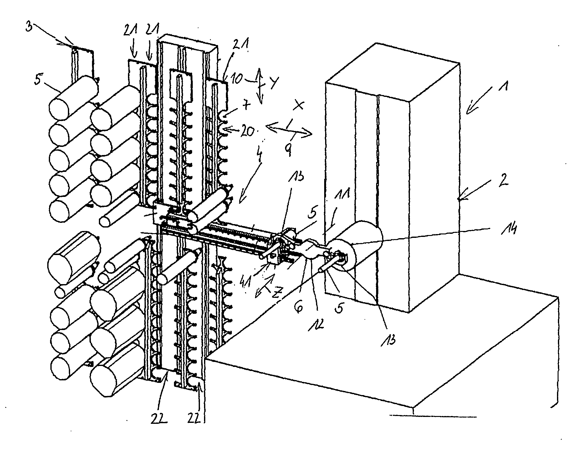
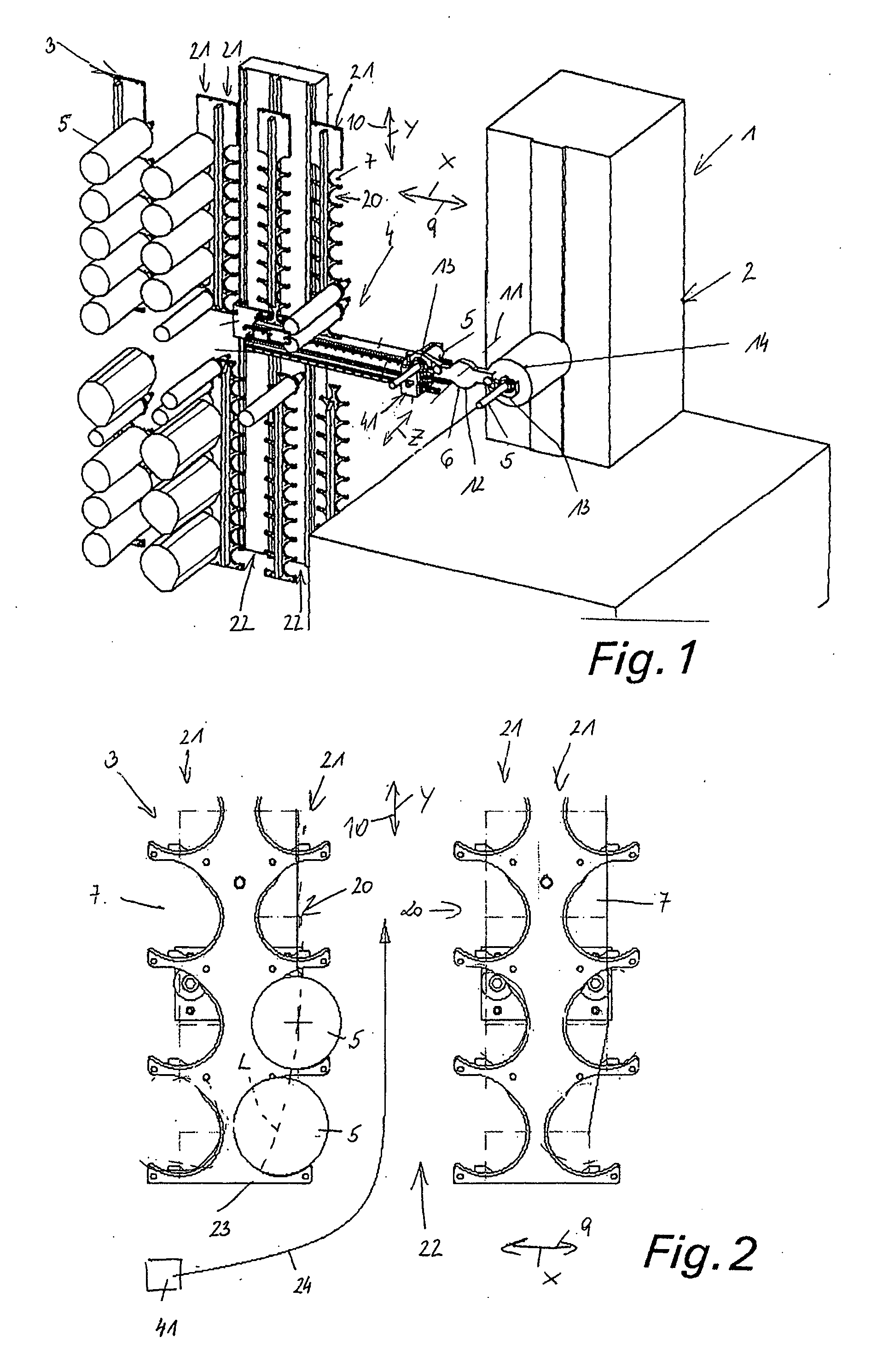
[0017] The processing center 1 comprises a machine tool 2, a tool store 3, formed in the exemplary embodiment by a matrix magazine, a manipulation device 4 for tools 5, and a tool changer 6. The tool store 3 has a number of openings 7 in corresponding storage elements for receiving tools 5. Multiple tools 5 are stored in an x-y coordinate system in the tool store 3.

[0018] The manipulation device 4, which is movable or pivotable along multiple axes x, y, z or directions, is used to remove the tools 5 from the tool store 3 and to transfer them to the tool changer 6, a first main movement in the horizontal direction x being indicated by the double arrow 9 and a second main movement in a direction y, which is inclined thereto, being indicated by the double arrow 10. The manipulation device 4 transfers or receives tools 5 to or from the tool changer 6, which has a changer circular head 12, pivotable around an axis 11, having two diametrically opposite grippers 13. The tool changer 6 pla...


PUM


Abstract

The present invention relates to a method for loading and unloading a machine tool with tools, the tools being stored in a tool store and being transported via a manipulation device, which is particularly movable along multiple axes, to a transfer position on the machine tool or in the machine tool and being removed therefrom after use, the tools being transported by a gripper device along at least one path in a first main movement direction and in at least one travel lane, which is formed by two rows spaced apart from one another and is inclined to the main movement direction. To shorten the tool changing times, a gripper device of the manipulation device is moved between a loading and unloading position of the tool along at least one continuously running, at least partially curved path.

Description

BACKGROUND OF THE INVENTION [0001] The present invention relates to a method for loading and unloading a machine tool with tools, the tools being stored in a tool store and being transported via a manipulation device, which is particularly movable along multiple axes, to a transfer position on the machine tool or in the machine tool and being removed therefrom after use, the tools being transported by a gripper device along at least one path in a first main movement direction and in at least one travel lane, which is formed by two rows spaced apart from one another and is inclined to the first main movement direction, a gripper device of the manipulation device being moved between a loading and unloading position of the tool along at least one continuously running, at least partially curved path. Furthermore, the present invention relates to a device for performing the method. [0002] In connection with automated loading and unloading of a machine tool in particular, such as a millin...

Claims


Application Information

Patent Timeline
Patent Type & Authority Applications(United States)
IPC IPC(8): B23Q3/155
CPCB23Q3/15526Y10T483/10Y10T483/1809B23Q3/15713B23Q3/15536
Inventor MUSER, JOSEFMUSER, ARMIN
Owner MUSER JOSEF
Why Eureka
Try Eureka