Method for detecting rotational speed

a technology of rotational speed and internal combustion engine, which is applied in the direction of machines/engines, electric control, instruments, etc., can solve the problems of negative effect on the dynamics of the rotational speed signal and the increase of error interference caused, and achieve the effect of less time delay

Inactive Publication Date: 2005-05-10
CONTINENTAL AUTOMOTIVE GMBH
View PDF6 Cites 2 Cited by
  • Summary
  • Abstract
  • Description
  • Claims
  • Application Information

AI Technical Summary

Benefits of technology

[0006]The invention therefore addresses the problem of specifying a method for detecting the rotational speed in an internal combustion engine, in which method the current rotational speed of the internal combustion engine can be ascertained with less time delay.
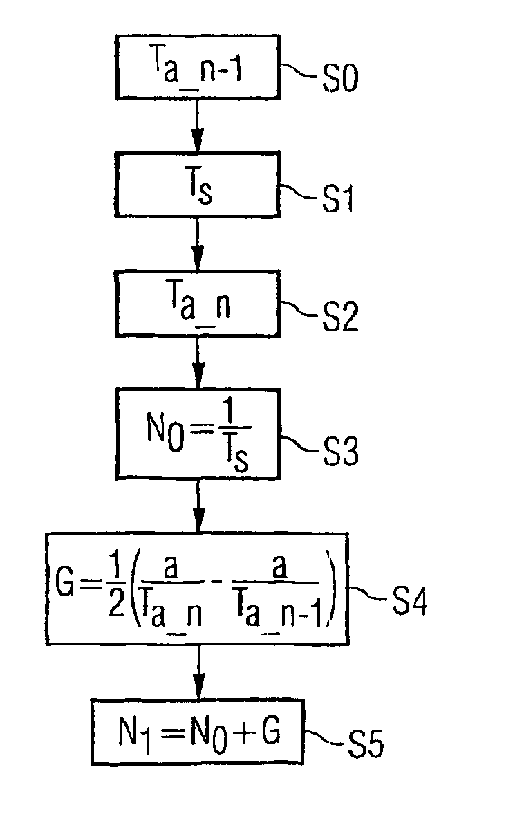
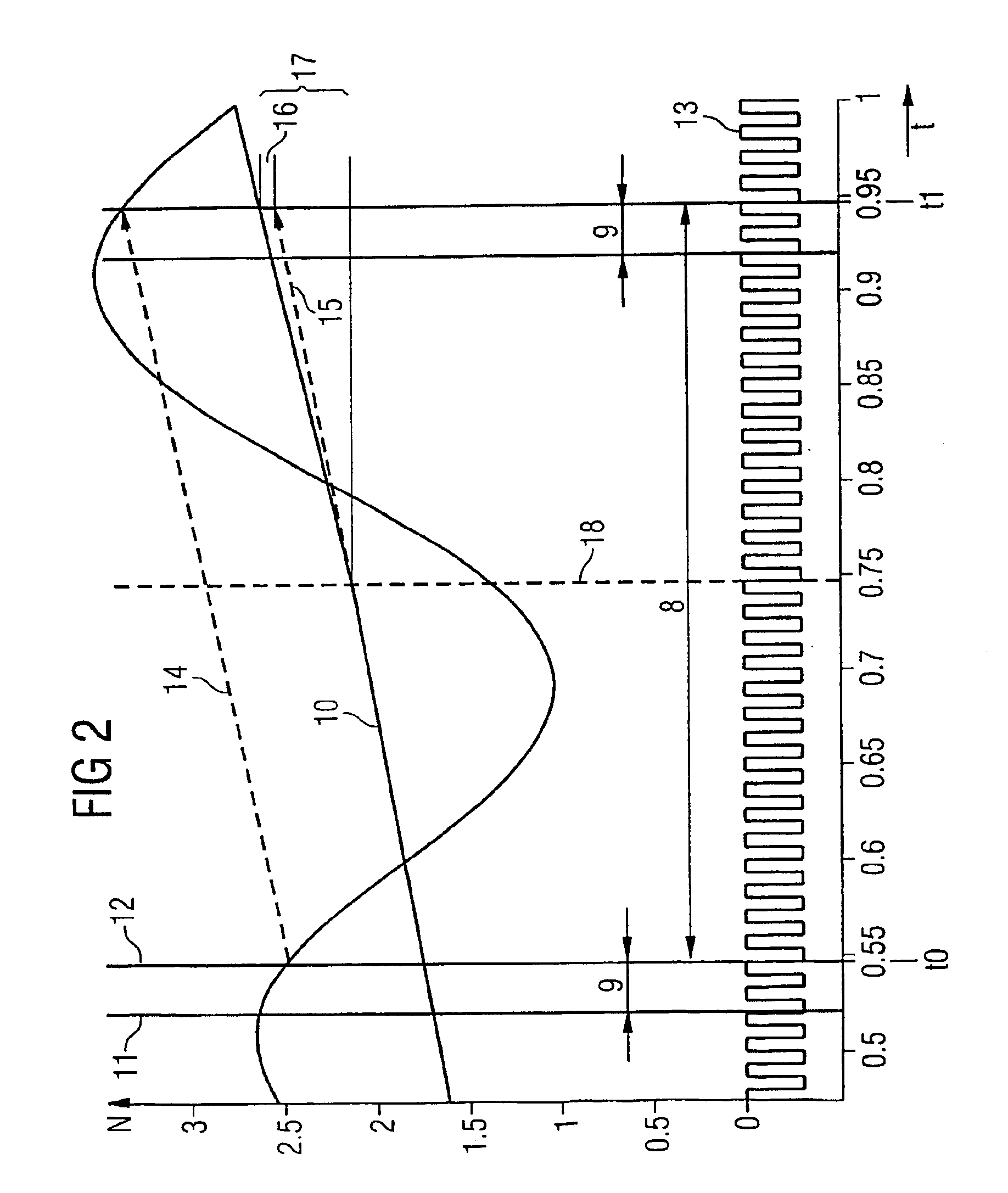
[0011]Therefore, as claimed in the invention, additional part-segment passes are detected and analyzed. Before and after ascertaining the rotational speed value from the duration of the pass of the segment, a part-segment pass is detected and a corresponding gradient is determined in each case. Since this gradient is ascertained with the assistance of small, extremely current part-segment passes, it allows the rotational speed value to be updated. Of course, it is not possible to infer the rotational speed from the part-segment passes alone, without errors being caused by the superimposition of high-frequency interferences on the rotational speed. However, the rotational speed value can be updated on the basis of the durations of the gradients of the part-segment passes. It is therefore possible to update the rotational speed value using these gradients, whereby a rotational speed signal is obtained which has almost zero dead time in comparison with conventional low-pass filtering or averaging. Such a signal has an advantageous effect on the dynamic properties of various control circuits during the operation of an internal combustion engine (e.g. controlling the idle speed).
[0017]Working out the difference has the further advantage that an additive association with the rotational speed value is possible in this case, and therefore an operation which is known to require little computing effort can be used.

Problems solved by technology

The shorter the scanned sector, the greater the error interference caused by these oscillations.
Furthermore, the detection of a segment of the sector wheel causes a certain averaging, which likewise has a negative effect on the dynamics of the rotational speed signal.

Method used


Image

  • Method for detecting rotational speed
  • Method for detecting rotational speed
  • Method for detecting rotational speed

Examples


Embodiment Construction

[0023]FIG. 1 is a schematic illustration of an internal combustion engine 1, whose operation is controlled by a control device 2 via lines which are not defined in detail. This control device 2 determines operating parameters of the internal combustion engine, e.g. the rotational speed N and the load, and assigns the internal combustion engine 1, which is a four-cylinder internal combustion engine in this schematically illustrated example, a quantity of fuel which is required for handling the operation.

[0024]The internal combustion engine 1 causes a crankshaft 3 to rotate, whereupon a motor vehicle (not shown) is driven. A sector wheel 4 having 60 teeth is arranged on the crankshaft 3. The teeth of the sector wheel 4 are sensed by an inductive or hall sensor 5, which conducts its signals to the control device 2 via lines which are not described.

[0025]By using the signals of the sensor 5, the control device 2 ascertains the information about the rotational speed N, said information b...


PUM


Abstract

In a method for detecting rotational speed of an internal combustion engine (1), a sector wheel (4) which is driven by the internal combustion engine (1) is scanned, the throughflow of a specific segment of the sector wheel is detected, the duration of said segment-throughflow is measured and a rotational speed value is determined therefrom. Additionally, the throughflow of a specific part of the segment is detected before and after determination of the rotational speed value and a gradient of the duration of the partial segment throughflow is determined in order to update the rotational speed value.

Description

CROSS REFERENCE TO RELATED APPLICATION[0001]This application is a continuation of copending International Application No. PCT / DE02 / 03302 filed Sep. 6, 2002 which designates the United States, and claims priority to German application no. 101 43 953.9 filed Sep. 7, 2001.TECHNICAL FIELD OF THE INVENTION[0002]The invention relates to a method for detecting a rotational speed of an internal combustion engine, wherein a sector wheel which is connected to a crankshaft is scanned and the duration of a pass of a segment of a sector wheel is ascertained in order to determine a rotational speed value, said segment having a specific size.DESCRIPTION OF THE RELATED ART[0003]Methods of this type for detecting rotational speed are usual in internal combustion engines, wherein it is normal to scan a toothed wheel having 60 teeth which is arranged on a crankshaft. As a result of the working principle of an internal combustion engine having continuous alternation between compression and expansion of...

Claims


Application Information

Patent Timeline
IPC IPC(8): F02D41/14G01P3/42G01P3/489
CPCG01P3/489F02D41/1403
Inventor BOHNIG, RALFPRZYMUSINSKI, ACHIMSTAHL, CHRISTIAN
Owner CONTINENTAL AUTOMOTIVE GMBH
Why Eureka
Try Eureka