Method and arrangement for the power supply of an induction heating device

a technology of induction heating and power supply, which is applied in the direction of dc-dc conversion, power conversion systems, instruments, etc., can solve the problems of complicated operating frequency change and distortion of power consumption from mains supply

Inactive Publication Date: 2010-03-30
E G O ELEKTRO GERAETEBAU GMBH
View PDF8 Cites 1 Cited by
  • Summary
  • Abstract
  • Description
  • Claims
  • Application Information

AI Technical Summary

Benefits of technology

[0017]Thus, it is possible by changing the pulse width ratio as a function of the course of the half-wave to counteract the formation of harmonics. Thus, with the operating frequency unchanged, it is possible to reduce the power level, so that a current flowing in a resonant circuit of the power supply can be kept proportional to the alternating supply voltage. Thus, the main supply reactions are reduced and higher power levels for the induction heating device are made possible.
[0018]In an advantageous embodiment of the invention the change to the pulse widths can be 10% to 40%. With particular advantage, the pulse widths are modified by a maximum of 25%, i.e., shortened or lengthened.
[0019]In a second embodiment of the invention, in all or two of the switching means present in a series resonant circuit both pulse widths are shortened in such a way that the dead times between them are lengthened. This also takes place during the course of a half-wave and up to the half-time of the half-wave the dead times are longer and subsequently shorter again. None of the switching means is controlled during these dead times. A change to the dead times is advantageously a maximum of 100%, i.e. at the most twice the dead times between the shortest dead times and the longest dead time. With particular advantage the maximum change is somewhat below this, for example 50% to 80%.
[0020]Also, through the lengthening of the dead times between the pulses for the switching means, the power level at the induction coil can be reduced somewhat in order to reduce harmonics and therefore reduce supply reactions.
[0021]A shortening of the on-times or pulse widths of the switching means takes place in the same way as the lengthening of the dead times advantageously symmetrically to the half-time of the half-wave. This allows a uniform control and power generation.
[0017]Thus, it is possible by changing the pulse width ratio as a function of the course of the half-wave to counteract the formation of harmonics. Thus, with the operating frequency unchanged, it is possible to reduce the power level, so that a current flowing in a resonant circuit of the power supply can be kept proportional to the alternating supply voltage. Thus, the main supply reactions are reduced and higher power levels for the induction heating device are made possible.
[0017]Thus, it is possible by changing the pulse width ratio as a function of the course of the half-wave to counteract the formation of harmonics. Thus, with the operating frequency unchanged, it is possible to reduce the power level, so that a current flowing in a resonant circuit of the power supply can be kept proportional to the alternating supply voltage. Thus, the main supply reactions are reduced and higher power levels for the induction heating device are made possible.
[0015]An alternating supply voltage is used for the power supply of the induction heating device. There is also a frequency converter with switchable switching means. An operating frequency of said switching means or said frequency converter remains the same over a half-wave of the alternating supply voltage. According to one embodiment of the invention, in a first basic development of the invention, a pulse width of the control device of the switching means or the frequency converter is modified during a half-wave. This is brought about in that up to the half-time of a half-wave, a pulse width of a first switching means is made shorter and a pulse width of another, second switching means is made longer. In the second half-time of the half-wave, the pulse widths are again modified in such a way that they are again of equal length up to the end of the half-wave. Preferably the sum of the pulse widths (G1, G2) remains the same. The change can admittedly take place asymmetrically to the half-time, but advantageously there is a change to the pulse widths symmetrically relative to the half-time.
[0014]This problem is solved in various embodiments by a method and arrangement as claimed herein. Advantageous and preferred developments of the invention form the subject matter of the further claims and are explained in greater detail hereinafter. Some of the subsequently mentioned features and characteristics apply both to the method and to the arrangement or the use. They are in part only described once, but independently thereof apply both to the method, the arrangement and the application or use. By express reference the wording of the claims is made into part of the content of the description.

Problems solved by technology

Thus, ultimately the power consumption from the mains supply is distorted and its curve diverges from the predetermined supply voltage curve.
However, this operating frequency change is complicated from the control standpoint.

Method used


Image

  • Method and arrangement for the power supply of an induction heating device
  • Method and arrangement for the power supply of an induction heating device
  • Method and arrangement for the power supply of an induction heating device

Examples


first embodiment

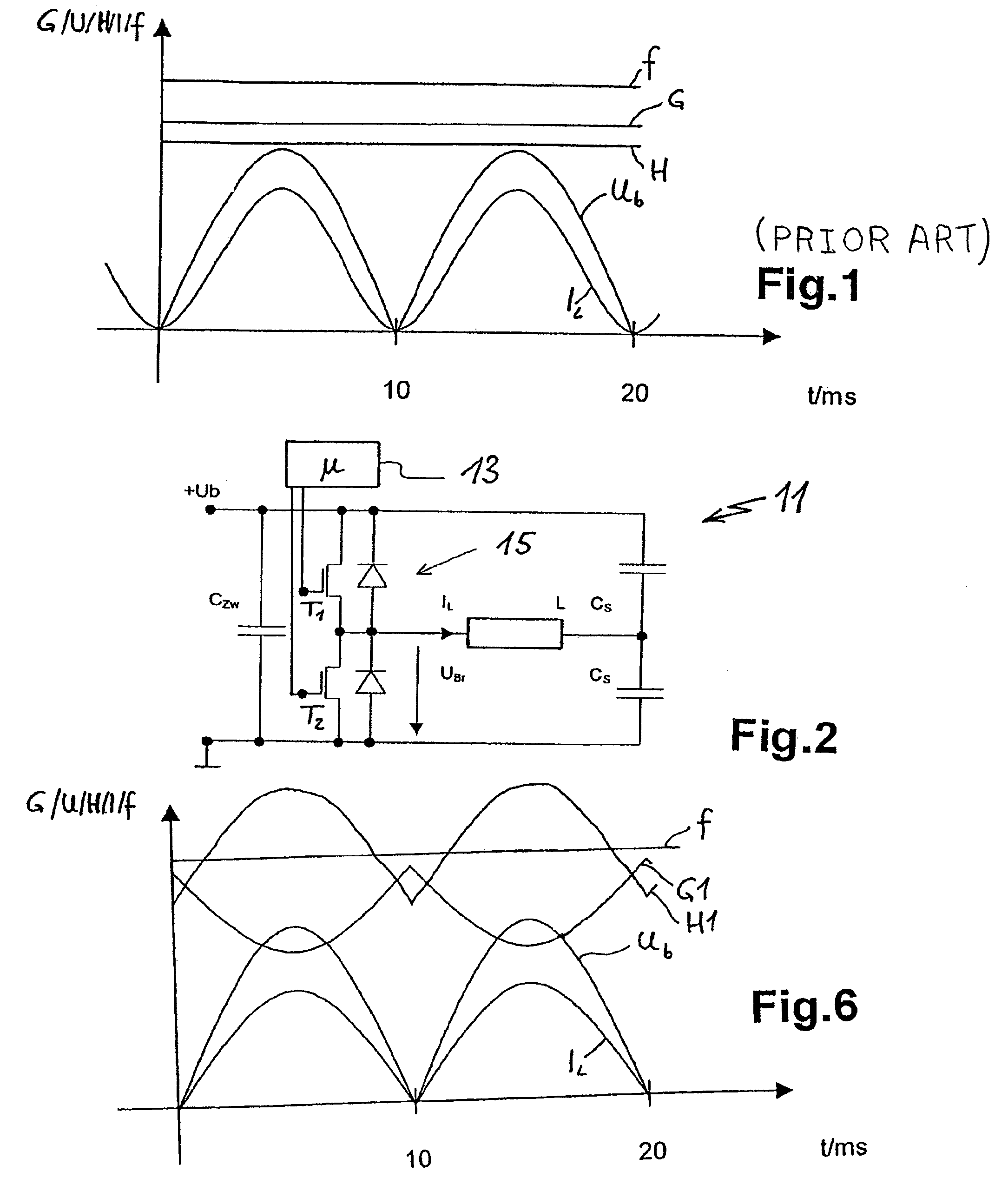
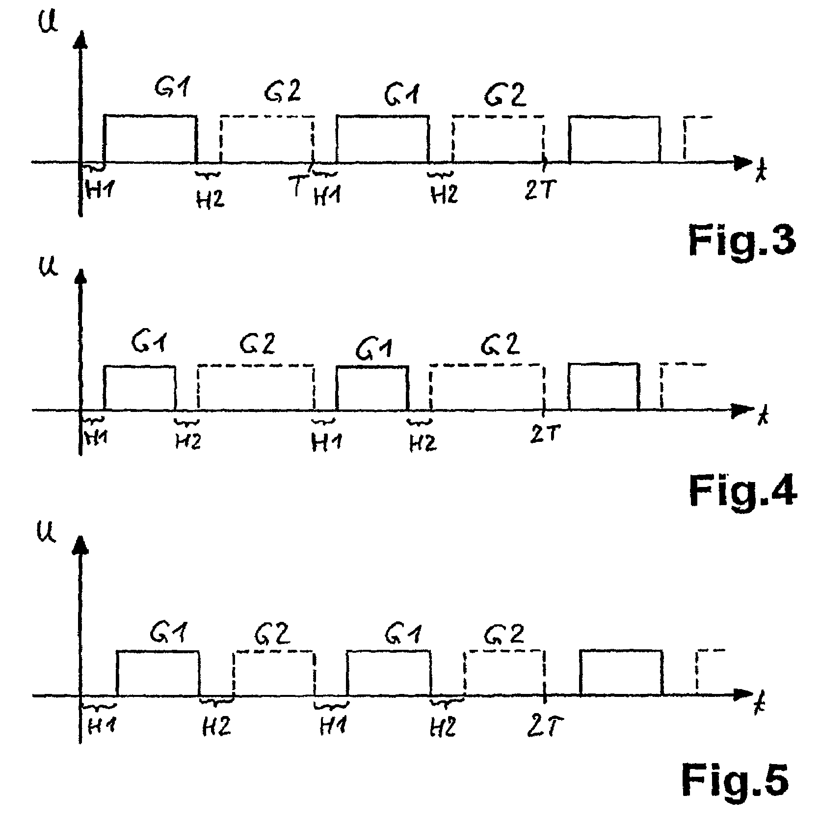
[0030]In accordance with the aforementioned, first embodiment of the invention in FIG. 4, the pulse widths are modified. This means that for the same dead times H1 and H2 the pulse widths at transistor T1, i.e. G1, have become shorter and are in fact shortened by approximately 25% close to the high point of a network half-wave. The pulse widths G2 at transistor T2 are lengthened by approximately 25%. As a result of these different pulse widths, the power level at the induction coil is reduced somewhat for an unchanged operating frequency f. As can be gathered from FIG. 6, the change to the pulse widths G1 is once again a sinusoidal curve or has a sinusoidal path. The minimum pulse width G1 is at the middle or high point of a network half-wave. The not shown path G2 is obtained on reflecting the path for G1 on a line which runs horizontally through the maximum values for G1 in such a way that the sum (G1+G2) is always constant.

second embodiment

[0031]In accordance with the invention, FIG. 5 shows that, diverging from FIG. 4, admittedly the pulse widths G1 and G2 remain the same, but the dead times H1 and H2 between them are changed. The dead times H1 and H2, i.e. prior to the given pulse width G1 and G2, are lengthened by approximately 60% compared with FIG. 3. Here again the diagrammatic path for H1 can be gathered from FIG. 6 and is the same for H2.

[0032]Also, with this method of modifying the dead times H, for a constant operating frequency it is possible to achieve a more sinusoidal or precisely sinusoidal power consumption IL and this effect can also be gathered from FIG. 6.

[0033]It is obvious that also both embodiment of the invention can be jointly used. In both cases, the change to the pulse width or dead time over a network or mains voltage half-wave should take place in an analogous or mirror symmetrical manner or in small steps. Thus, on the one hand it is possible to reduce or prevent the formation of harmonics...


PUM


Abstract

In order to increase the power of an induction heating device or in order to avoid system reactions when driving the latter, either the pulse widths of the two switching means can be made unsymmetrical in the case of half-bridge driving up to the half-point of a half-cycle. Alternatively, a dead time between the pulse width can be extended. This advantageously takes place without interruption and continuously. In the course of a half-cycle, the power is thus reduced given an unaltered operating frequency and an inductor current has virtually an ideal sine-wave form.

Description

CROSS REFERENCE TO RELATED APPLICATIONS[0001]This application is a continuation of PCT / EP2007 / 007350, filed Aug. 21, 2007, which in turn claims priority to DE 10 2006 041 964.2, filed on Aug. 25, 2006, the contents of both of which are incorporated by reference.FIELD OF THE INVENTION[0002]The invention relates to a method for the power supply of an induction heating device and to an arrangement for the power supply to an induction heating device.BACKGROUND OF THE INVENTION[0003]Such induction heating devices are, for example, used as induction coils in induction hobs. The wish is always for ever higher power levels, in particular so as to be able to rapidly carry out the boiling of larger quantities of liquid, for example, for cooking noodles.[0004]At present there is a limit of approximately 3.2 kW, as from which the frequency converters necessary for the power supply exceed the value limits established by standards with regards to harmonics and mains supply reactions. The reason f...

Claims


Application Information

Patent Timeline
Patent Type & Authority Patents(United States)
IPC IPC(8): H02M3/335
CPCH05B6/062
Inventor BOGEL, JORG
Owner E G O ELEKTRO GERAETEBAU GMBH
Why Eureka
Try Eureka