
Low frequency noise reduction circuit architecture for communications applications

Active Publication Date: 2008-03-20
AVAGO TECH INT SALES PTE LTD
View PDF13 Cites 153 Cited by
  • Summary
  • Abstract
  • Description
  • Claims
  • Application Information

AI Technical Summary

Benefits of technology

[0012]Use of the above architecture provides several benefits. First, by combining the existing AC coupling capacitances with integrated on-chip resistors, an economical yet effective high-pass filter can be achieved. Second, by using programmable resistors, an adaptive high-pass filter can be achieved. Third, by incorporating the programmable resistors inside the equalization loop, the compressed in-band voice signals can be equalized. Finally, by adopting the resistance topology of the current invention, the input-referred noise of the PGA can be maintained at a low level over a wide dynamic range.

Problems solved by technology

This type of low frequency ambient noise and / or wind turbulence noise, commonly referred to as wind noise, has posed special problems in communications applications.
For example, in the case of a portable headset microphone, wind noise amplitude can be very large, compared with the speech levels.
Based on the sound sensing characteristic of the human ears, the lower frequency noise reduces one's ability to discern sounds at frequencies above the noise frequencies if the low frequency noise power is significantly higher than the voice power.
However, such an implementation severely distorts the sound characteristic.
When the wind noise is strong, the adaptive process will cause the poles of the dynamic filter to fall within the audio band.
As a consequence, the low frequency content of the desired audio is compressed, which in turn reduces voice intelligibility and sound fidelity.
This in turn demands large capacitance values and significant silicon utilization.
However, such a silicon requirement is too big to be practical for consumer electronics applications.
However, there are a number of disadvantages with this approach.
Firstly, the circuitry itself contributes a significant amount of noise.
Such a minimum limitation places a further limitation on the ability of the high pass filter formed by the input resistance and the AC coupling capacitance to effectively reduce the effects of the wind noise.

Method used


Image

  • Low frequency noise reduction circuit architecture for communications applications
  • Low frequency noise reduction circuit architecture for communications applications
  • Low frequency noise reduction circuit architecture for communications applications

Examples


Embodiment Construction

[0034]While the present invention is described herein with reference to illustrative embodiments for particular applications, it should be understood that the invention is not limited thereto. Those skilled in the art with access to the teachings provided herein will recognize additional modifications, applications, and embodiments within the scope thereof and additional fields in which the present invention would be of significant utility.

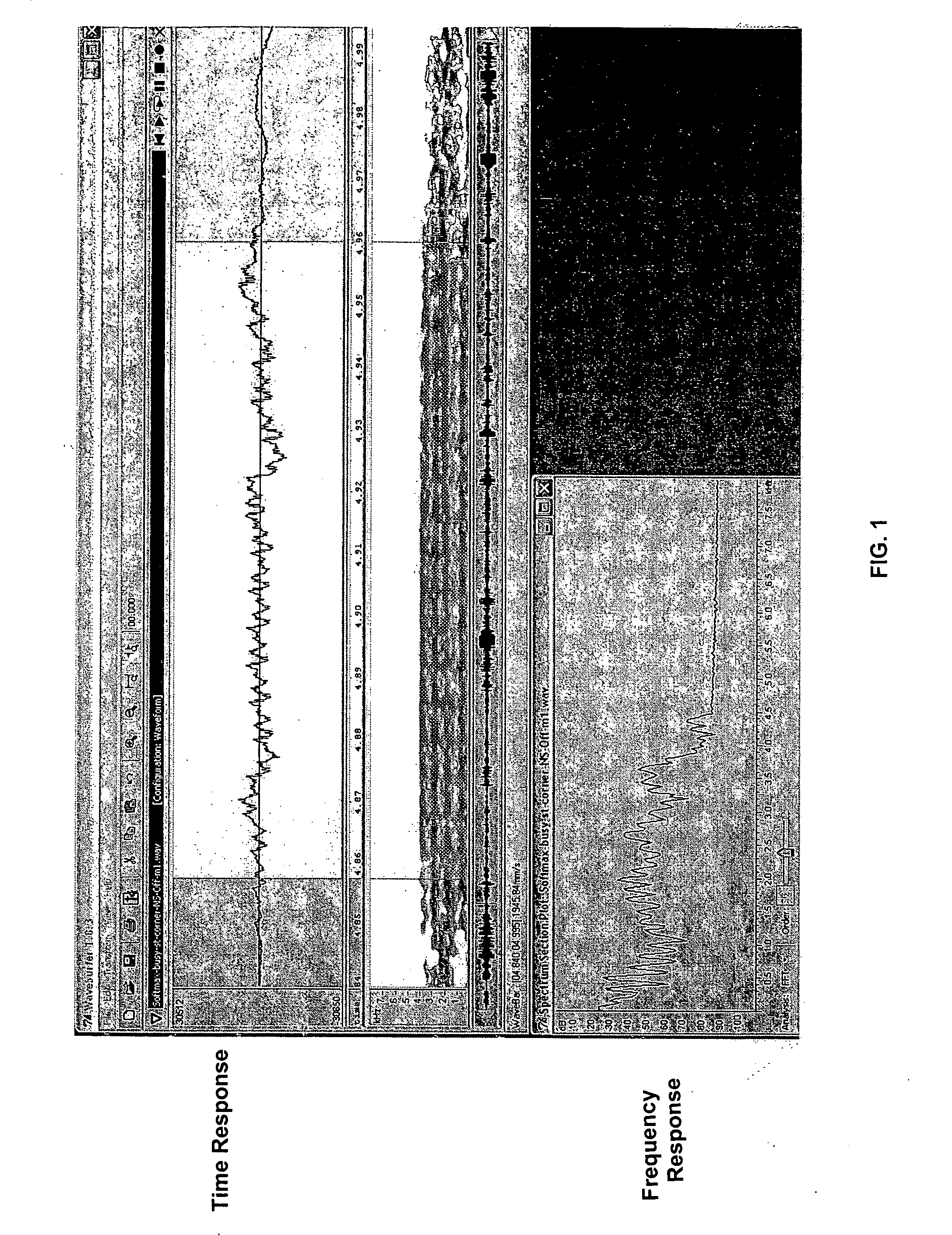
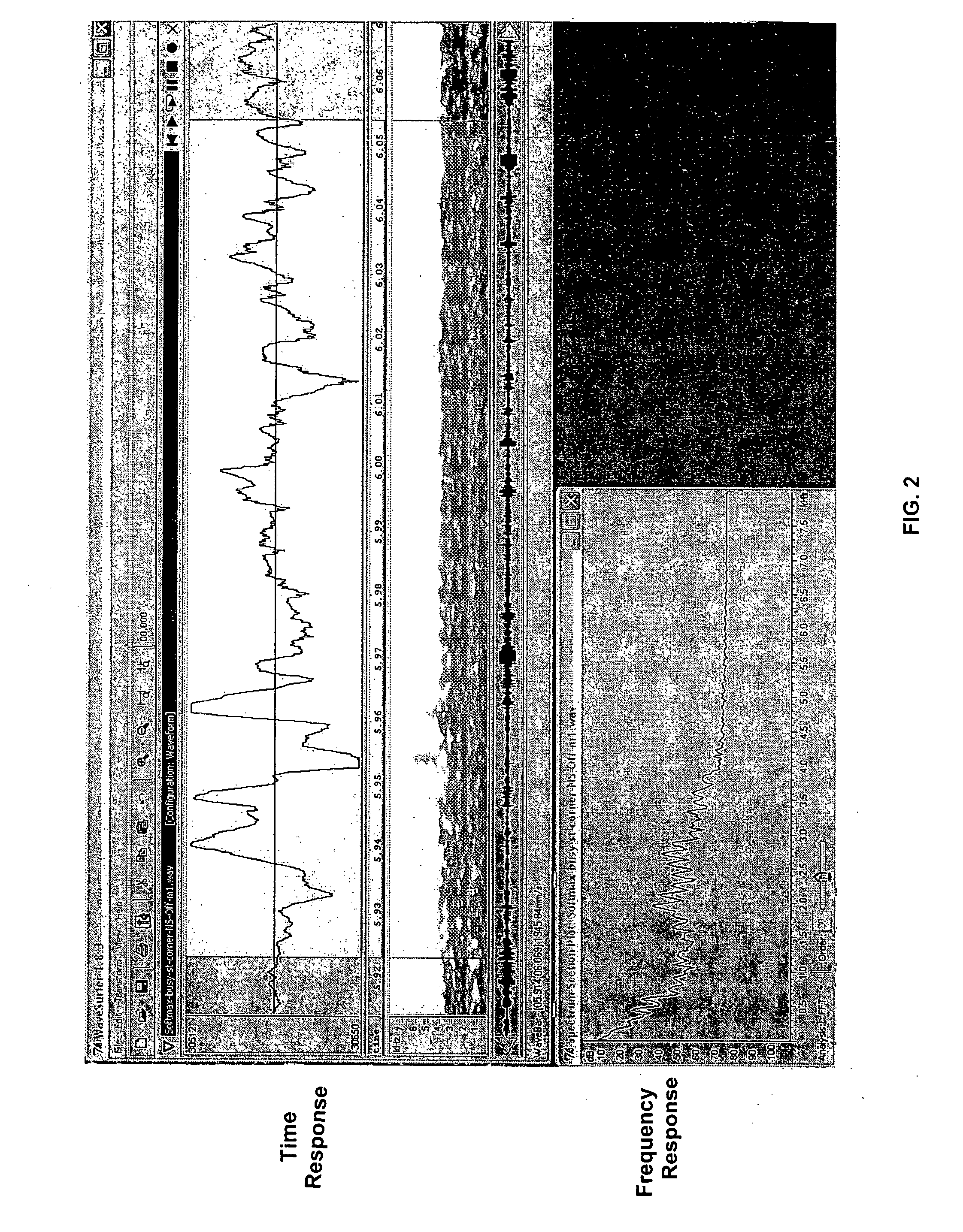
[0035]In voice communication systems, significant low frequency noise can affect the fidelity of the audio signals transmitted. FIG. 1 is a plot of the time response 110 and the frequency response 120 of a typical speech segment without wind noise. FIG. 2 is a plot of the time response 210 and frequency response 220 of a typical speech segment, but now with an added strong wind noise component. A strong wind noise can have a power level approximately 10 dB to 30 dB higher than the typical talker voice level. As noted by comparing FIGS. 1 and 2, wi...


PUM


Abstract

A noise reduction circuit for reducing the effects of low frequency noise such as wind noise in communications applications is described. In one embodiment, the noise reduction circuit features a high pass filter formed by exploiting the existing off-chip AC coupling capacitances in making the connection to the source of audio signals. The filter may be adaptive to environmental low frequency noise level through programming the shunt resistances. A low-noise wide dynamic range programmable gain amplifier is also described. Adaptive equalization of the audio signal is also described through the utilization of programmable front-end resistors and a back-end audio equalizer.

Description

BACKGROUND OF THE INVENTION[0001]1. Field of the Invention[0002]The present invention relates to noise reduction circuit architecture, more particularly, to providing a noise reduction circuit architecture for communications applications.[0003]2. Related Art[0004]Typically, wind, air conditioning, and busy traffic introduce significant noise energy at frequencies below 150 Hz, compared with the energy levels of human voices over the bandwidth 300 Hz to 3,400 Hz. This type of low frequency ambient noise and / or wind turbulence noise, commonly referred to as wind noise, has posed special problems in communications applications.[0005]For example, in the case of a portable headset microphone, wind noise amplitude can be very large, compared with the speech levels. A strong wind noise has a power level approximately 10 dB to 30 dB higher than the power level of a typical human voice. Wind noise generally has a frequency less than 1 kHz, and the lower the frequency, the higher the noise po...

Claims


Application Information

Patent Timeline
IPC IPC(8): H04B15/00
CPCH04R3/04
Inventor JIANG, XICHENGSONG, JUNGWOOCHEN, JIANLONG
Owner AVAGO TECH INT SALES PTE LTD
Learn More