Eureka AIR delivers breakthrough ideas for toughest innovation challenges, trusted by R&D personnel around the world.

Ankle joint exoskeleton based on elastic element rigidity switching mechanism

A technology of switching mechanism and elastic element, applied in the direction of equipment to help people move, physical therapy, etc., can solve the problems of increasing metabolic energy consumption, poor auxiliary effect, etc., and achieve the effect of increasing the amount of spring deformation

Active Publication Date: 2018-03-30
HUAZHONG UNIV OF SCI & TECH
View PDF3 Cites 22 Cited by
  • Summary
  • Abstract
  • Description
  • Claims
  • Application Information

AI Technical Summary

Problems solved by technology

On the other hand, in the support phase, the greater the stiffness of the elastic element, the better the auxiliary effect, but when the stiffness of the elastic element exceeds a certain value, it will increase the muscle activity of antagonist muscles and increase the consumption of metabolic energy
[0005] In the prior art, the elastic element is used to simulate the Achilles tendon of the ankle joint. The maximum elongation of the elastic element is limited by the three-dimensional geometric parameters of the human body. Under the same expected auxiliary effect, the stiffness of the spring element has a minimum value. When the expected auxiliary effect is relatively high, The stiffness of the elastic element will increase the muscle activity of the antagonist muscle, increase the consumption of metabolic energy, and make the assisting effect poor

Method used


Image

  • Ankle joint exoskeleton based on elastic element rigidity switching mechanism
  • Ankle joint exoskeleton based on elastic element rigidity switching mechanism
  • Ankle joint exoskeleton based on elastic element rigidity switching mechanism

Examples


Embodiment Construction

[0030] In order to make the object, technical solution and advantages of the present invention clearer, the present invention will be further described in detail below in conjunction with the accompanying drawings and embodiments. It should be understood that the specific embodiments described here are only used to explain the present invention, not to limit the present invention. In addition, the technical features involved in the various embodiments of the present invention described below can be combined with each other as long as they do not constitute a conflict with each other.

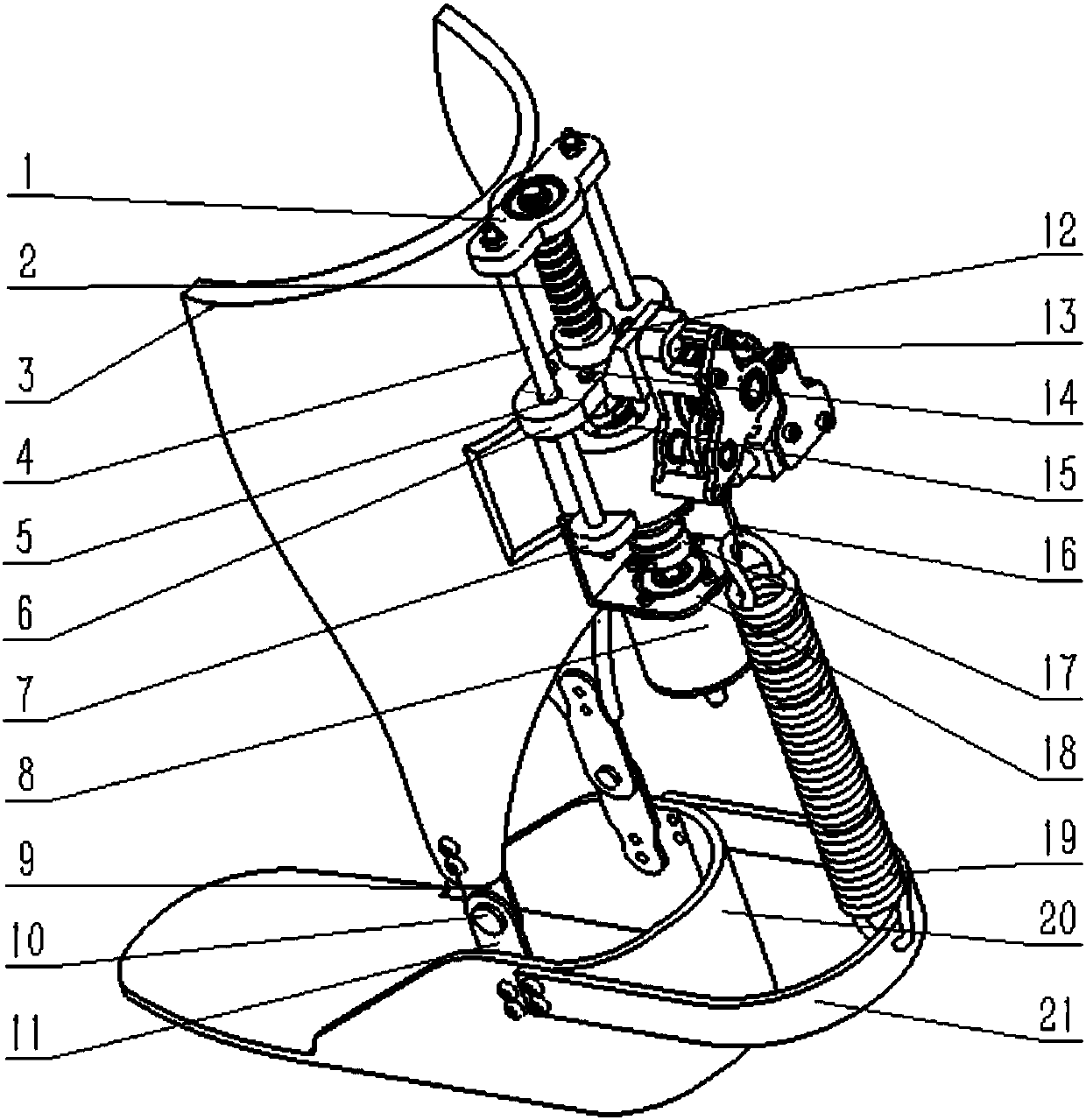
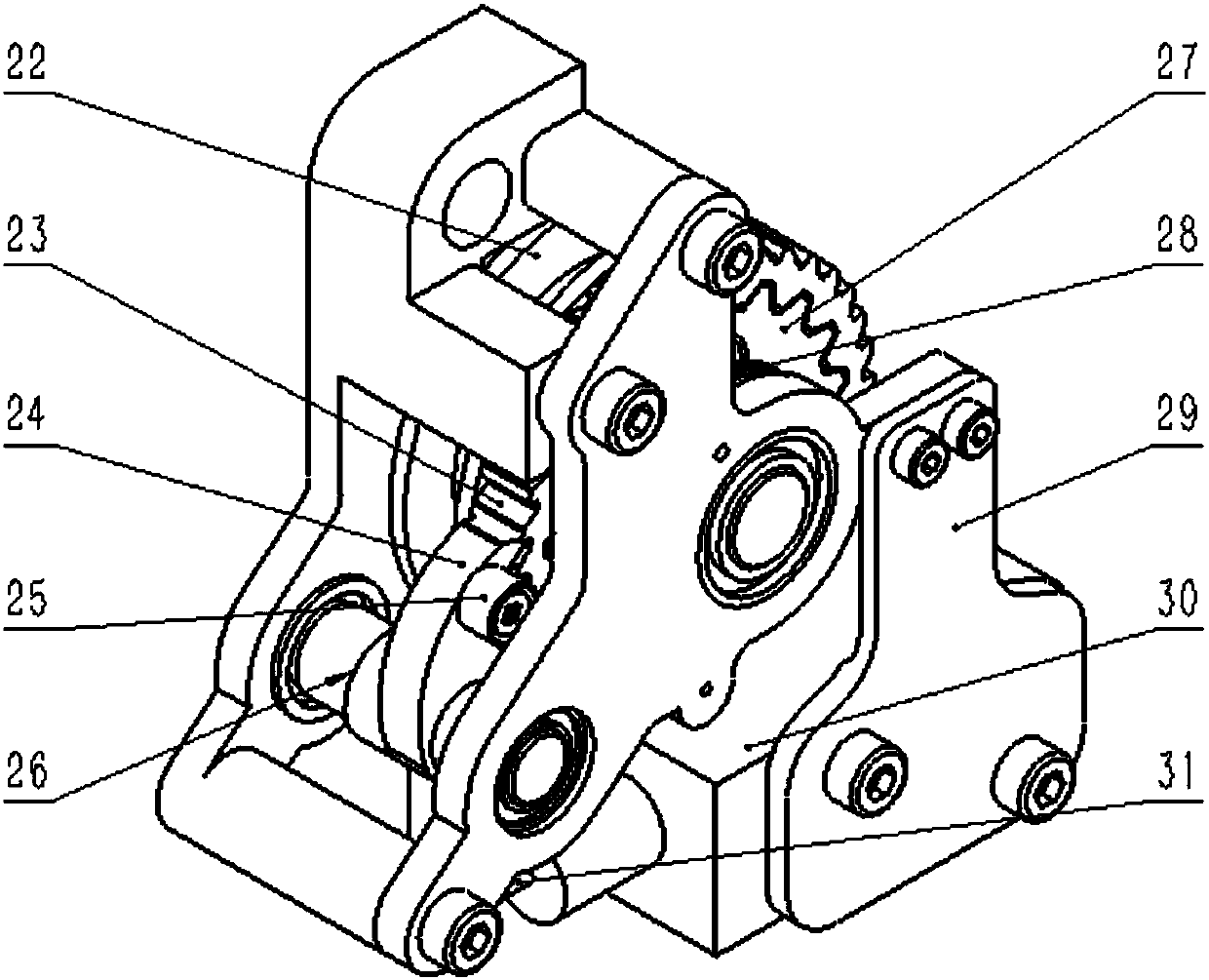
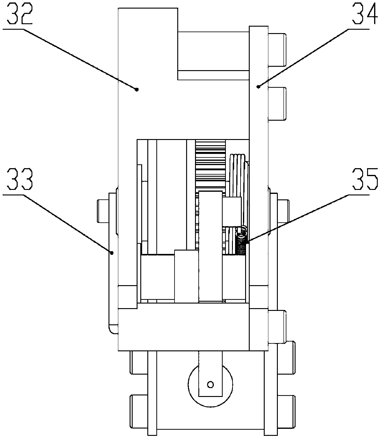
[0031] refer to Figure 1 ~ Figure 3 , an ankle joint exoskeleton based on an elastic element stiffness switching mechanism, including a calf brace 3, a foot rest 20, a spring bracket 21, a motor bracket 18, a motor 8, a ball screw mechanism, a tension spring 19, and a return spring 35 , through-type electromagnet 30, ratchet bracket and ratchet mechanism, wherein,

[0032] The foot support 20...


PUM


Abstract

The invention belongs to the technical field of lower limb exoskeleton robots, and discloses an ankle joint exoskeleton based on an elastic element rigidity switching mechanism. The ankle joint exoskeleton based on the elastic element rigidity switching mechanism comprises a shank brace, a foot support, a spring support, a motor support, a motor, a ball screw mechanism, an extension spring, a return spring, a penetrating type electromagnet, a ratchet wheel support and a ratchet wheel mechanism, wherein the ratchet wheel mechanism comprises a ratchet wheel and a pawl; the penetrating type electromagnet is mounted on the ratchet wheel support; one end of the return spring is connected with the pawl while the other end of the return spring is mounted on the ratchet wheel support; the lower end of the extension spring is mounted on the spring support while the upper end of the extension spring is connected and wound onto a pulley through a rope; and the pulley is arranged on a ratchet shaft. By the extension spring, a unique energy storage process of achilles tendon and an energy releasing mode can be simulated effectively, an elastic element rigidity switching function can be fulfilled on the basis of a human gait movement rule, thus, an elastic element conforms to time-variant characteristics of in-gait and inter-gait of human movement, three-dimensional geometrical parameter limitation can be broken through, and deformation of the elastic element is improved.

Description

technical field [0001] The invention belongs to the technical field of lower extremity exoskeleton robots, and more particularly relates to an ankle joint exoskeleton based on an elastic element stiffness switching mechanism. Background technique [0002] In daily life, human beings walk an average of 10,000 steps per day. The existence of external environmental factors such as air resistance and sole damping make people consume more energy while walking than any other activity in a day. In addition, long-term walking causes Muscle fatigue will reduce the efficiency of human exercise and increase the energy consumption of the human body, which is especially true for the elderly, disabled and other people with limited mobility. Therefore, it is of great research significance and value to develop a human-assisted walking system to improve human walking efficiency and meet the walking needs of the elderly and disabled. [0003] The ankle joint is a joint that shifts the center...

Claims


Application Information

Patent Timeline
IPC IPC(8): A61H3/00
CPCA61H3/00A61H2003/007A61H2201/0196A61H2201/1207A61H2201/14A61H2201/1642
Inventor 张琴刘冲冲黄波熊蔡华
Owner HUAZHONG UNIV OF SCI & TECH
Why Eureka
Eureka Blog
Learn More