Device and method for generating chaotic signal

a technology of chaotic signal and device, which is applied in the direction of digital transmission, pulse generation with predetermined statistical distribution, securing communication, etc., can solve the problems of device difficulties in generating a stable chaotic signal, chaotic signal cannot be stably generated, and signal phase not clear

Inactive Publication Date: 2008-03-20
SAMSUNG ELECTRO MECHANICS CO LTD
View PDF4 Cites 7 Cited by
  • Summary
  • Abstract
  • Description
  • Claims
  • Application Information

AI Technical Summary

Benefits of technology

[0021] An advantage of the present invention is that it provides a device and a method for generating a chaotic signal, in which a digital-type PN signal generator is used to stably generate a chaotic signal regardless of a process change.
[0022] Additional aspect and advantages of the present general inventive concept will be set forth in part in the description which follows and, in part, will be obvious from the description, or may be learned by practice of the general inventive concept.
[0023] According to an aspect of the invention, a device for generating a chaotic signal comprises a PN signal generator that is composed of a digital logic circuit and generates a digital pseudo random signal with a predetermined frequency; a voltage control that generates a clock signal with a predetermined frequency; a mixer that mixes the pseudo random signal and the clock signal so as to generate a chaotic signal to output; and a band-pass filter that filters the chaotic signal, output from the mixer, into a chaotic signal of a desired band and then outputs the filtered signal.
[0024] Preferably, the PN signal generator is composed of a digital logic circuit, including N (N is a positive number) D-flip flops and a gate unit, and generates a predetermined bit number (2N-1) of pseudo random signals.
[0025] Preferably, each of the D-flip flops includes an even number of inverters and switches and, in accordance with an applied sine-wave signal, outputs an input signal without phase inversion.
[0026] Preferably, the gate unit receives an output of the (N-1)th D-flip flop and an output of the Nth D-flip flop so as to generate a signal for an input of the first D-flip flop. Further, the gate unit is composed of an X-OR gate.

Problems solved by technology

However, since a chaotic signal has an aperiodic characteristic like noise, the chaotic signal does not have a clear phase.
Therefore, the device has difficulties in generating a stable chaotic signal.
Accordingly, a chaotic signal cannot be stably generated, which means that the device is sensitive to a process change.

Method used


Image

  • Device and method for generating chaotic signal
  • Device and method for generating chaotic signal
  • Device and method for generating chaotic signal

Examples


Embodiment Construction

[0048] Reference will now be made in detail to the embodiments of the present general inventive concept, examples of which are illustrated in the accompanying drawings, wherein like reference numerals refer to like elements throughout. The embodiments are described below in order to explain the present general inventive concept by referring to the figures.

[0049] Hereinafter, a preferred embodiment of the present invention will be described in detail with reference to the accompanying drawings.

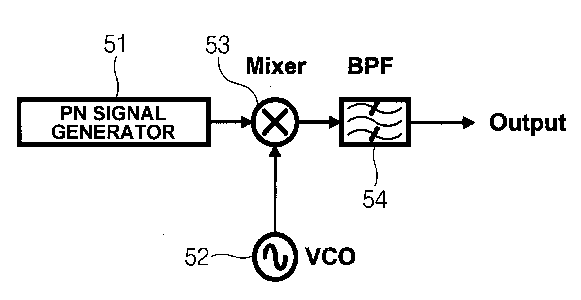
[0050]FIG. 5 is a block diagram of a device for generating a chaotic signal according to an embodiment of the invention. As shown in FIG. 5, the device for generating a chaotic signal includes a PN signal generator 51, a voltage control oscillator 52, a mixer 53, and a band-pass filter 54.

[0051] The PN signal generator 51 composed of a digital logic circuit generates a digital pseudo random signal with a predetermined frequency.

[0052]FIG. 6 is a diagram showing the structure of the PN signa...


PUM


Abstract

Provided is a device for generating a chaotic signal comprising a PN signal generator that is composed of a digital logic circuit and generates a digital pseudo random signal with a predetermined frequency; a voltage control that generates a clock signal with a predetermined frequency; a mixer that mixes the pseudo random signal and the clock signal so as to generate a chaotic signal to output; and a band-pass filter that filters the chaotic signal, output from the mixer, into a chaotic signal of a desired band and then outputs the filtered signal.

Description

CROSS-REFERENCE TO RELATED APPLICATIONS [0001] This application claims the benefit of Korean Patent Application No. 10-2006-0076593 filed with the Korea Intellectual Property Office on Aug. 14, 2006, the disclosure of which is incorporated herein by reference. BACKGROUND OF THE INVENTION [0002] 1. Field of the Invention [0003] The present invention relates to a device and a method for generating a chaotic signal, which are applied to Ultra Wide Band (hereinafter, referred to as ‘UWB’) communication using an On-Off Keying (OOK) scheme. In the device and the method, a digital-type PN signal generator is used to stably generate a chaotic signal regardless of a process change. [0004] 2. Description of the Related Art [0005] In general, the UWB is referred to as a frequency band where a frequency bandwidth occupies more than 25% of a center frequency or is more than 500 MHz. [0006] When the UWB is observed at a time axis, it can be found that the UWB has a very small signal width. Theref...

Claims


Application Information

Patent Timeline
Patent Type & Authority Applications(United States)
IPC IPC(8): H04L9/22
CPCH03K3/84H04B1/69H04L27/04H04B1/7174H04B1/71632H04B1/04
Inventor KIM, YU SINMYUNG, NO CHULMOON, JEONG HOJEONG, MOO ILLEE, CHANG SEOKYANG, CHANG SOOLEE, KWANG DUPARK, SANG GYU
Owner SAMSUNG ELECTRO MECHANICS CO LTD
Why Eureka
Try Eureka