
Adaptive anisotropic filtering of projection data for computed tomography

a computed tomography and anisotropic filtering technology, applied in image enhancement, instruments, applications, etc., can solve the problems of less efficient post processing approaches in reducing noise induced streak artifacts, and achieve the effect of reducing high frequency nois

Active Publication Date: 2008-03-20
THE BOARD OF TRUSTEES OF THE LELAND STANFORD JUNIOR UNIV
View PDF20 Cites 20 Cited by
  • Summary
  • Abstract
  • Description
  • Claims
  • Application Information

AI Technical Summary

Benefits of technology

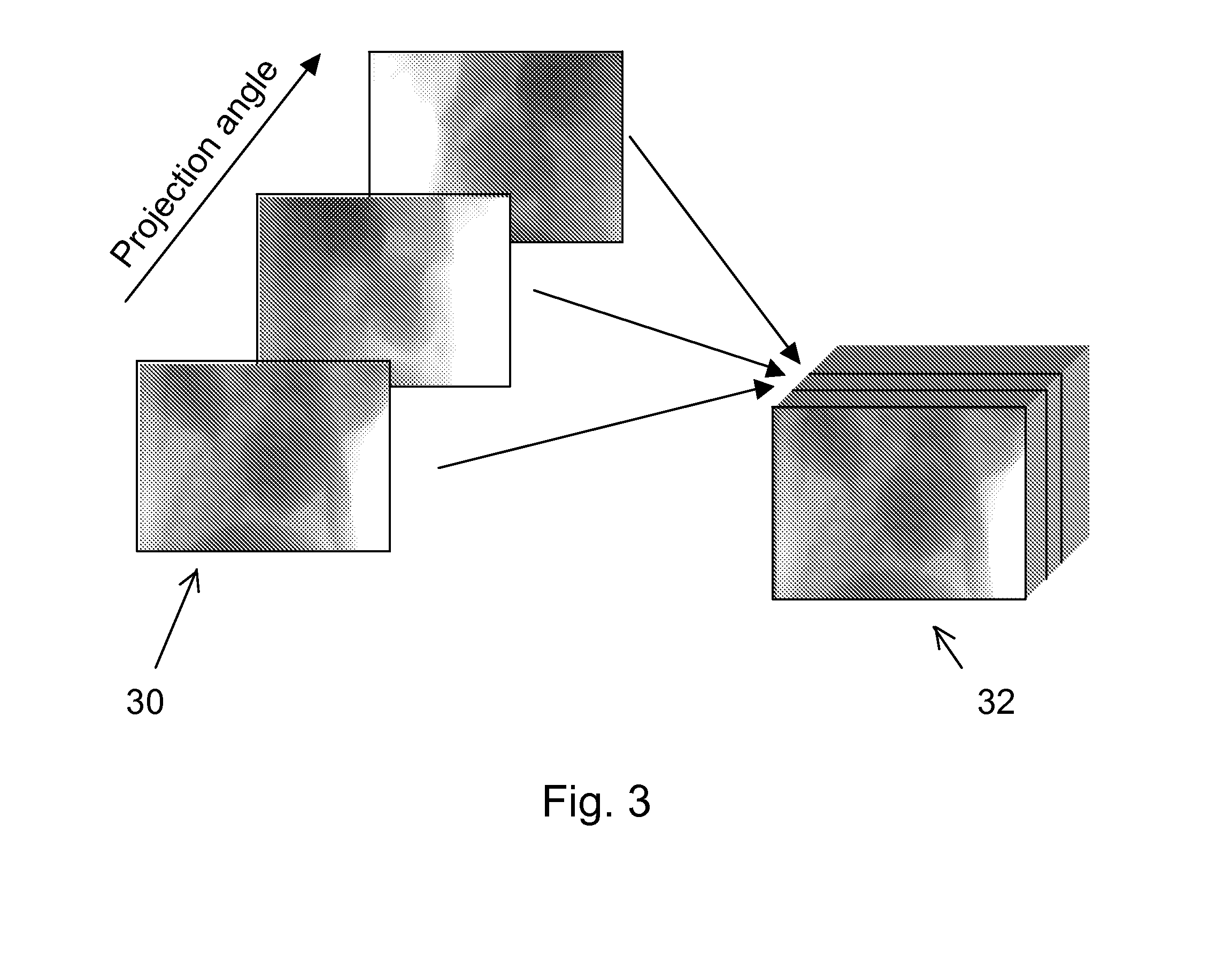
[0008]In accordance with the invention, anisotropic filtering of a stack of projection data is performed prior to image reconstruction. In a computed tomography application, a 3D stack of projection data includes multiple 2D projections acquired at different angles of rotation. The orientation of structures within the 3D space is estimated using a set of differently oriented filters, for example. The obtained representation of the local orientation is utilized to control the anisotropic filtering of the data in order to apply low pass filtering along structures while maintaining all frequency components perpendicular to the structures. Thus, the low pass filtering will reduce the high frequency noise to a degree determined by the estimated strength and continuity of structures in projection space. The direction of low pass filtering is also locally controlled by the estimated orientation. The invention is applicable to tomosynthesis, also, where the source or detector is translated rather than rotated.
[0009]The invention allows a substantial reduction in radiation dose required for obtaining 3D CT image data. Alternatively, improved image quality can be attained at a given radiation dose. The invention can be applied to four dimensions to process a time sequence of 3D projection data.

Problems solved by technology

However, post processing approaches will be less efficient in reducing for example noise induced streak artifacts compared to processing prior to image reconstruction.

Method used


Image

  • Adaptive anisotropic filtering of projection data for computed tomography
  • Adaptive anisotropic filtering of projection data for computed tomography
  • Adaptive anisotropic filtering of projection data for computed tomography

Examples


Embodiment Construction

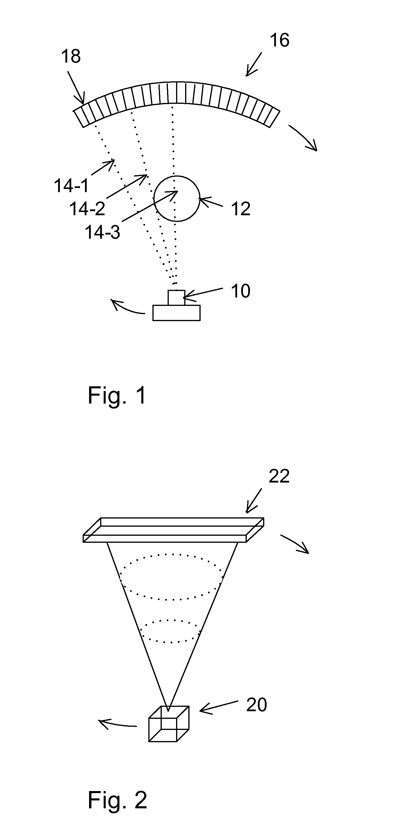
[0017]FIG. 1 is a schematic diagram of CT apparatus including an x-ray source 10 and an x-ray detector 20 which are rotatibly translated around an object 12 with detector 20 providing measurement of attenuated x-rays passing through object 12 and providing data for reconstructing an image of a slice through object 12. The x-ray source emits a fan or cone shaped beam towards a scan object such as a patient, and the beam after being attenuated by the scan object impinges upon an array of radiation detectors, which in turn produce electrical signals indicative of the attenuated beam. Multiple sources could also be used to generate a parallel x-ray beam, or a single narrow beam could be scanned across the object. The electrical signals are then transmitted to a data processing unit for analysis and image reconstruction.

[0018]As illustrated, a portion of the x-ray beam 14-1 travels directly to a detector element 22 in the array 20 without passing through object 12, a portion of the x-ray...


PUM

PropertyMeasurementUnit
frequencyaaaaaaaaaa
CTaaaaaaaaaa
computed tomographyaaaaaaaaaa

Abstract

CT imaging is enhanced by adaptively filtering x-ray attenuation data prior to image reconstruction. Detected x-ray projection data are adaptively and anisotropically filtered based on the locally estimated orientation of structures within the projection data from an object being imaged at a plurality of rotation positions. The detected x-ray data are uniformly low pass filtered to preserve the local mean values in the data, while the high pass filtering is controlled based on the estimated orientations. The resulting filtered data provide projection data with smoothing along the structures while maintaining sharpness along edges. Image noise and noise induced streak artifacts are reduced without increased blurring along edges in the reconstructed images. The enhanced image allows reduced x-ray dose while maintaining image quality.

Description

GOVERNMENT RIGHTS[0001]The U.S. Government has rights in the disclosed invention pursuant to NIH Grant No. 003524 to Stanford University.BACKGROUND OF THE INVENTION[0002]This invention relates generally to computed tomography (CT) and more particularly the invention relates to processing of CT image data to reduce adverse noise effects in data acquired using a low x-ray dose.[0003]Cross-sectional images of a patient using x-ray computed tomography have long been employed in medical practice. Briefly, computed tomography is the reconstruction by computer of a tomographic slice or a three-dimensional (3D) image volume of an object or patient. It is generated from multiple x-ray absorption measurements in a scan made around the object's periphery. These projections can be obtained using, for example, a conventional CT scanner with an x-ray source and a detector rotating at a relatively high speed, or with a source and a detector mounted on a C-arm that rotates more slowly around the pa...

Claims


Application Information

Patent Timeline
Patent Type & Authority Applications(United States)
IPC IPC(8): H05G1/60A61B6/00G01N23/00G21K1/12
CPCA61B6/032G06T11/005G06T2207/10081G06T2207/30004G06T5/20G06T2207/20012G06T2207/20192G06T5/002G06T5/70
Inventor WIGSTROM, LARSFAHRIG, REBECCA
Owner THE BOARD OF TRUSTEES OF THE LELAND STANFORD JUNIOR UNIV
Learn More