
High refractive index crystalline colloidal arrays materials and a process for making the same

Active Publication Date: 2008-03-13
UNIVERSITY OF PITTSBURGH
View PDF4 Cites 15 Cited by
  • Summary
  • Abstract
  • Description
  • Claims
  • Application Information

AI Technical Summary

Benefits of technology

[0021] Further, the invention provides for methods of coating the core particles to provide sufficient charge for the self-assembly of crystalline colloidal arrays, as well as to enable long time stability of the formed CCAs. Preferred embodiments comprise coating ZnS particles with highly charged polymeric shells.
[0025] Compared to existing CCA's made from other materials, the present invention of ZnS CCA has greatly increased the refractive index contrast between the particle and the surrounding medium, thus greatly increasing the diffraction intensity and efficiency as well as the band width of the diffracted wavelength. Furthermore, one of the invented coating methods (coating method #1) greatly simplifies the procedure of putting charges onto the core particles, and is cost effective and time conserving, as well as less hazardous to health.

Problems solved by technology

Such lattices have a low refractive index mismatch with the surrounding water, leading to modest diffraction efficiency.
Although this method yields highly diffracting media, it encompasses several disadvantages: 1) the lattices lack mechanical stability due to annealing deformations at high temperature; 2) the lattices have high defect density due to annealing and etching defects; 3) the annealed material is highly rigid, thus biologically compatible molecules cannot be readily introduced into the array for sensor applications; and 4) the high refractive index of the material is usually introduced by costly methods such as sputtering.
Thus the yield is low and the possibility to control the particle size is limited.
However, it is impossible to apply this method directly to ZnS particles, as the oligomers in the solution would not attach to the ZnS surface.
However, although particles may be coated this way in aqueous solutions, they do not readily form crystalline structures, as the repulsive forces between the particles are usually insufficient for the particles to stabilize, either due to insufficient surface charge, or due to the screening of salt ions and other impurities.
Even if such a crystalline order could temporarily form, it usually decays very quickly.
It had been suggested that continuous washing and time wear also causes polyelectrolyte chains to fall off multi-layer shells.
Additionally, multi-layer coating induces bridging of different shells, which is fatal for the formation of CCA.

Method used


Image

  • High refractive index crystalline colloidal arrays materials and a process for making the same
  • High refractive index crystalline colloidal arrays materials and a process for making the same
  • High refractive index crystalline colloidal arrays materials and a process for making the same

Examples


example 1

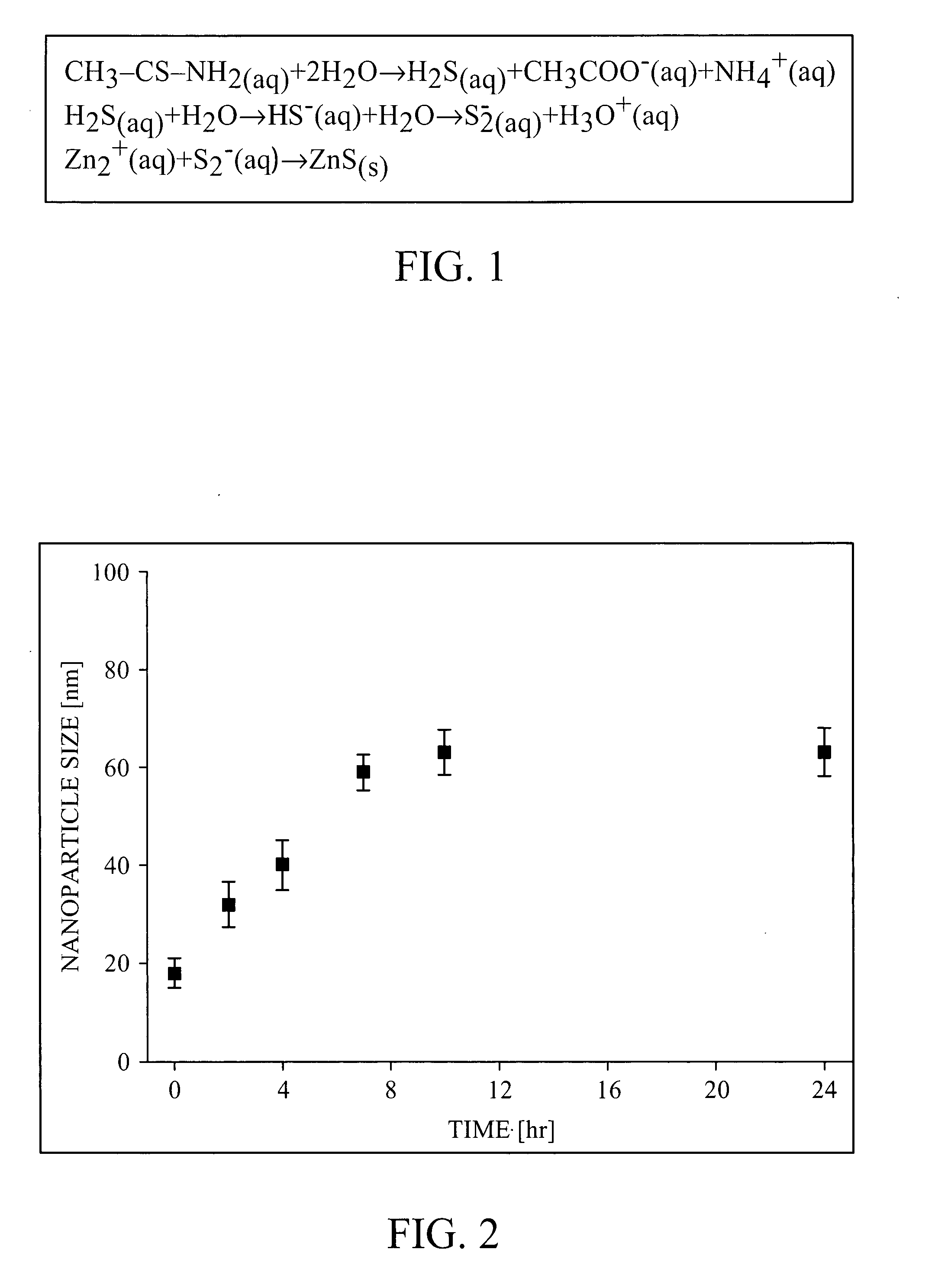
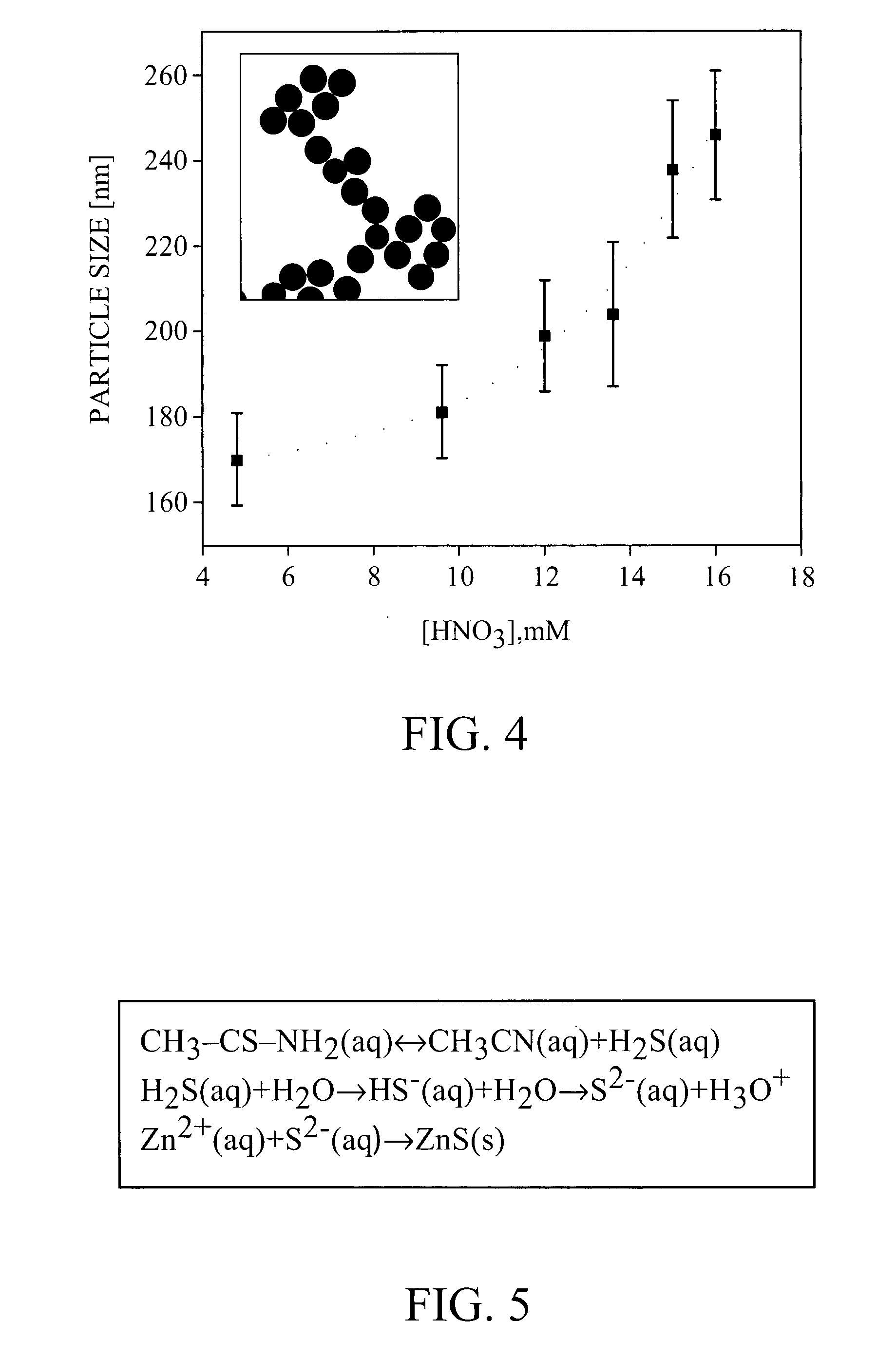
[0085] 4.44 g Zinc nitrate and 11.28 g thioacetamide (TAA) were allowed to react at room temperature in ethylene glycol with 20 wt % acidic water (comprising 5 mM nitric acid). After 18 hours of seeding, 18±2 nm ZnS nanoparticles were formed. The solution mixture was heated to 70° C. Particle size was controlled by the reaction time or the nitric acid concentration and can be tuned in the range of 130-300 nm. The reaction vessel was then cooled down in ice-water bath. After complete cool down, the particles in the solution were centrifuged and re-dispersed in 50 ml ethanol. At that point, particle size was determined by transmission electron microscopy (TEM). After 28 minutes of incubation at 70° C., the particle size was 187±13 nm (standard deviation ˜7%). A refractive index of 2 was estimated from the reflectance spectrum of a closed packed layer of these particles.

example 2

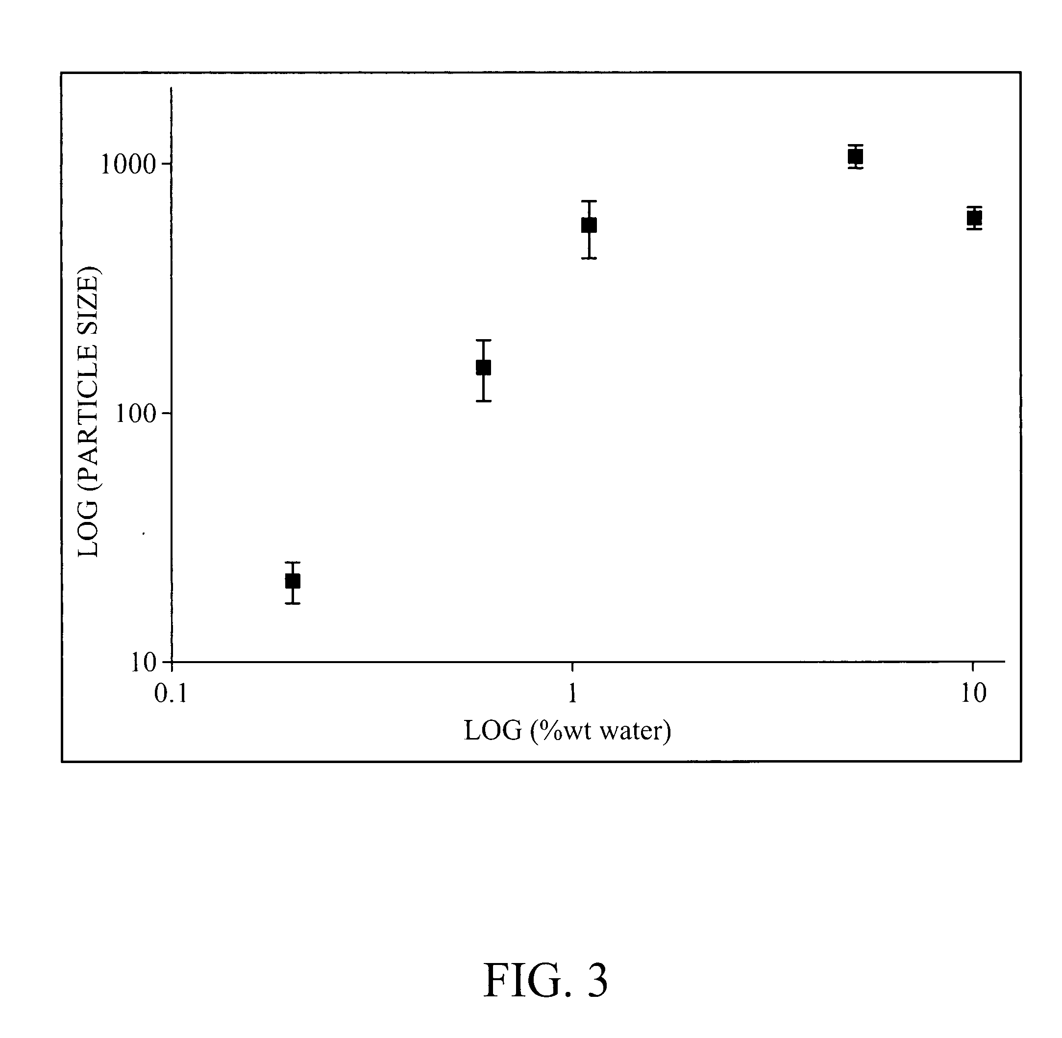
[0086] While the process for preparing monodisperse ZnS particles was optimized using 20 wt % water in the reaction, it is possible to perform the synthesis using different water concentrations by optimizing the amount of thioacetamide (TAA), the reaction temperature and the reaction duration to control the release of sulfur during the reaction. As an example, precipitation of ZnS in ethylene glycol with 0.6 wt % water at 70° C. with 0.8 mM HNO3, 0.25M TAA and 0.025M Zn(NO3)2 yielded highly monodisperse particles with an average size of 134 nm±14 nm (See FIG. 14).

example 3

[0087] 4.44 g zinc nitrate and 11.28 g thioacetamide were allowed to react at room temperature in ethylene glycol with 20 wt % acidic water (comprising 5 mM nitric acid). After 18 hours of seeding, 18±2 nm ZnS nanoparticles were formed. The solution mixture was then heated to 75° C. The reaction vessel was cooled down in ice-water bath. After complete cool down, the particles in the solution were centrifuged and re-dispersed in 50 ml ethanol. At that point, particle size was determined by TEM. After 28 minutes of incubation at 75° C., the particle size was 268±14 nm (standard deviation ˜5%). (See FIG. 15.) A refractive index of 2.2 was estimated from the reflectance spectrum of a close packed layer of these particles.


PUM

PropertyMeasurementUnit
Diameteraaaaaaaaaa
Diameteraaaaaaaaaa
Molar densityaaaaaaaaaa

Abstract

Disclosed are a new composite material and a process for synthesizing highly charged, highly monodisperse, core-shell particles with high refractive index cores, as well as stable, long lasting crystalline colloidal arrays (CCAs) formed thereof. A preferred embodiment of the core particle can be highly monodisperse zinc sulfide (ZnS) particles and a preferred embodiment of the shell can be highly charged polyelectrolytes. The CCAs formed thereof are charge stabilized photonic crystals that shows distinctive first and second order Bragg diffraction peaks whose locations vary over a wide spectral region from UV through visible to IR, with unusually strong intensity and broad band width due to the high index of refraction. These high refractive index particles are useful in applications such as optical filters, optical coatings, cosmetics and photonic crystals sensors and devices.

Description

CROSS-REFERENCE TO RELATED APPLICATIONS [0001] The present application claims the benefit of U.S. application Ser. No. 60 / 834,507 entitled High refractive index crystalline colloidal arrays materials and a process for making the same, filed Jul. 31, 2006, the entirety of which is hereby incorporated by reference.[0002] This invention was made with government support under Contract No. 2RO1 DK555348-03A1 awarded by the National Institutes of Health and under Contract No. FA8650-05-2-5042 awarded by the U.S. Air Force. Therefore, the government has certain rights in the invention.BACKGROUND OF THE INVENTION [0003] 1. Field of the Invention [0004] The present invention generally relates to crystalline colloidal arrays (CCAs) comprising core-shell particles composed of an inorganic, high refractive index core and a highly charged polymeric layer surrounding the core. The present invention further relates to methods of making the same. The invention also relates to optical filters, optic...

Claims


Application Information

Patent Timeline
IPC IPC(8): C08K9/06C01G9/08C08K9/04
CPCB01J13/16B82Y30/00C01G9/02C01G9/08C01P2004/32C30B29/605C01P2004/84C01P2006/40C30B5/00C30B29/48C01P2004/64
Inventor BEN-MOSHE, MATTIASHER, SANFORD A.QU, DANLUO, JLA
Owner UNIVERSITY OF PITTSBURGH
Learn More