Cerebral aneurysm stent and manufacturing method therefor

Pending Publication Date: 2022-06-23
S&G BIOTECH
View PDF0 Cites 0 Cited by
  • Summary
  • Abstract
  • Description
  • Claims
  • Application Information

AI Technical Summary

Benefits of technology

The present invention provides a new type of stent for treating cerebral aneurysms that solves problems with conventional Y-shaped overlapping stents. The new stent has a tubular shape, reducing the risk of complications and obstacles to expansion. It also prevents escape of the coil and allows for easy adjustment of the installation position and recovery of the stent. The manufacturing method is efficient and convenient. Overall, the new stent simplifies the stent-assisted coil embolization procedure and ensures better treatment outcomes.

Problems solved by technology

However, recently believed is that cerebral aneurysms mainly come from acquired factors, such as stress, vasculitis, and damage to vessel walls due to injury.
These cerebral aneurysms usually rupture without any symptoms and are expressed as cerebral hemorrhage, leading to death or very serious sequelae.
Further, the meninges are stimulated by bleeding, which may cause vomiting, nausea, severe headache, and stiff neck.
In severe cases, pressure within the skull increases, resulting in loss of consciousness or coma.
However, if complete clipping is impossible due to a bad position or shape, surgery is performed, with the remaining area covered with special gauze to serve as a buffer for possible bleeding.
However, in the case of a large-diameter cerebral aneurysm, the coil may escape off the cerebral aneurysm, and the cerebral aneurysm may recur after the procedure.
However, in the conventional stent-assisted coil embolization, two stents are overlapped in a Y-shape for a cerebral aneurysm occurring in branching vessels, so the procedure is complicated and requires a high-level surgical technique for clinicians.
There is also a problem of an increase in the risk of complications due to the use of two stents.
Further, there is a problem that the overlap of the two stents causes expansion difficult.

Method used


Image

  • Cerebral aneurysm stent and manufacturing method therefor
  • Cerebral aneurysm stent and manufacturing method therefor
  • Cerebral aneurysm stent and manufacturing method therefor

Examples


Embodiment Construction

Technical Problems

[0010]In view of the foregoing issues, the present invention aims to address the problems with the conventional cerebral aneurysm stent and provide a cerebral aneurysm stent applicable to T-shaped branching vessels and a method for manufacturing the same.

Means to Address the Problems

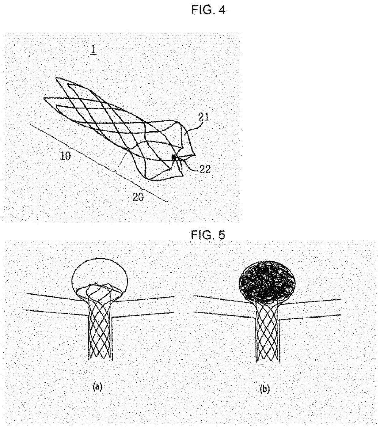
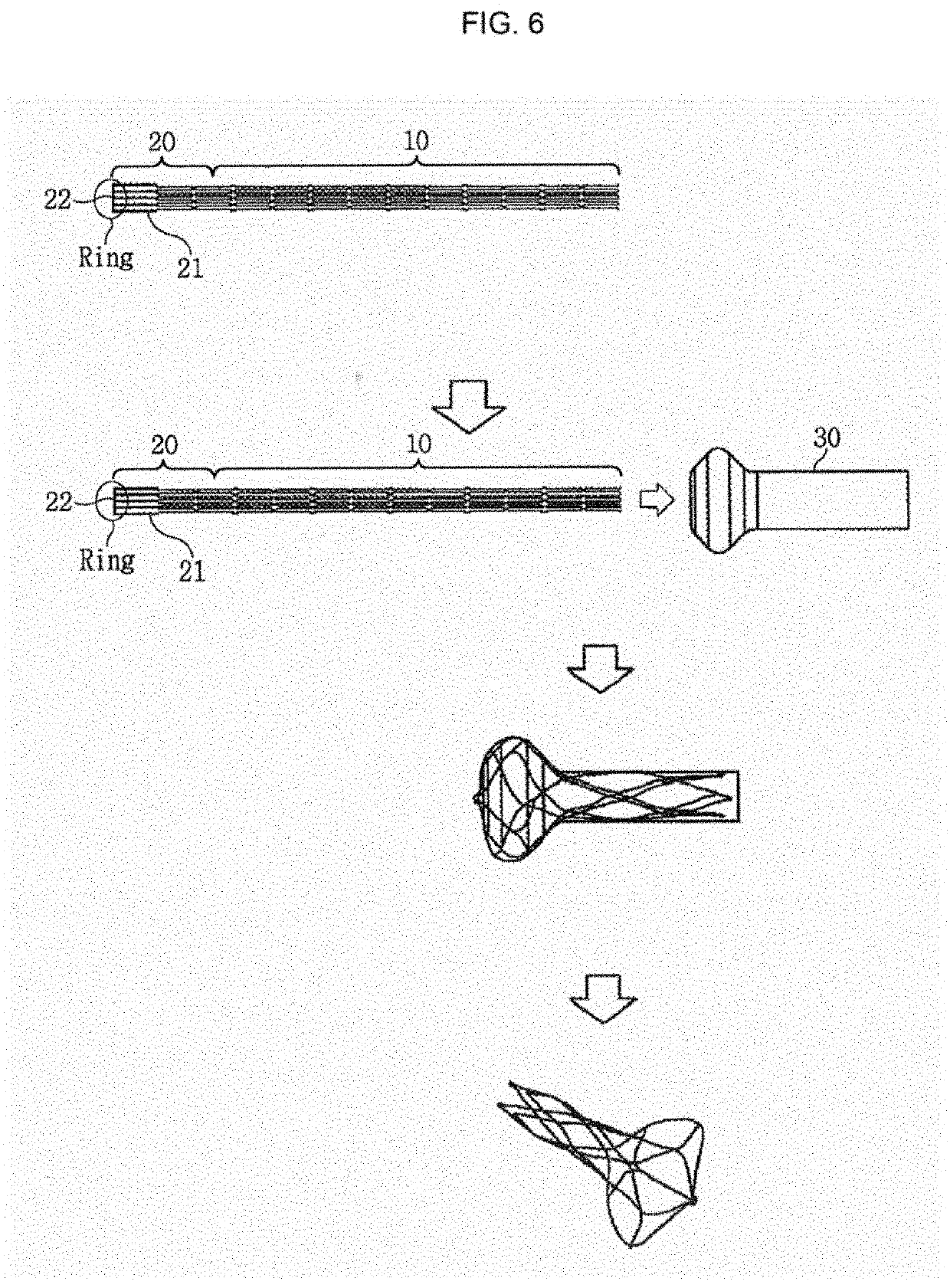
[0011]A cerebral aneurysm stent of the present invention comprises a hollow tubular main body and a coil support integrally formed with the main body, at a longitudinal end of the main body. The coil support includes a closed structure for a radial inner side of the cerebral aneurysm stent, at a longitudinal outer end of the cerebral aneurysm stent.

[0012]Further, according to an embodiment of the present invention, when the cerebral aneurysm stent is expanded, the coil support is expanded radially in a larger size than the main body, and the coil support is disposed in a cerebral aneurysm to support a coil inserted in the cerebral aneurysm. When the cerebral aneurysm stent is expanded, ...


PUM


Abstract

A cerebral aneurysm stent (1) of the present invention comprises a hollow tubular main body (10) and a coil support (20) integrally formed with the main body (10) at one end of the main body (10) in the longitudinal direction, wherein the coil support (20) comprises a closed structure (21) with respect to the radially inner side of the cerebral aneurysm stent (1), the closed structure (21) being located at an outer end portion of the cerebral aneurysm stent (1) in the longitudinal direction.

Description

TECHNICAL FIELD[0001]The present invention relates to a cerebral aneurysm stent for cerebral aneurysm embolization and a method for manufacturing the same, and more particularly, to a cerebral aneurysm stent for stent-assisted coil cerebral aneurysm embolization and a method for manufacturing the same, which uses a stent to prevent a coil inserted into a cerebral aneurysm formed in a branching vessel area.BACKGROUND ART[0002]A cerebral aneurysm is a vascular disease in which the blood vessel walls in the brain have microscopic cracks and abnormally swell. The exact cause is not yet known. In the past, cerebral aneurysms were known as resulting from innate factors, such as weak vessel walls. However, recently believed is that cerebral aneurysms mainly come from acquired factors, such as stress, vasculitis, and damage to vessel walls due to injury. These cerebral aneurysms usually rupture without any symptoms and are expressed as cerebral hemorrhage, leading to death or very serious s...

Claims


Application Information

Patent Timeline
IPC IPC(8): A61B17/12A61F2/91B21F45/00
CPCA61B17/12118A61B17/1214A61F2002/823B21F45/008A61F2/91A61F2/82A61B17/12113A61B2017/00526A61B2090/3966A61B2017/00867A61B17/12172A61F2240/004A61L31/022A61L31/14A61L31/18A61F2/844A61F2250/0098A61F2210/0014A61F2240/002A61F2240/001
Inventor KANG, SUNG KWON
Owner S&G BIOTECH
Why Eureka
Try Eureka