
Method and system for generating electric function test case

A technology for functional testing and generating systems, which is applied in software testing/debugging, electrical digital data processing, error detection/correction, etc. It can solve problems such as low coverage, lower test quality, automotive electrical functions, and hidden safety hazards. The effects of low coverage, overcoming poor test quality, and ensuring coverage and consistency

Active Publication Date: 2017-05-17
CHINA FIRST AUTOMOBILE
View PDF3 Cites 7 Cited by
  • Summary
  • Abstract
  • Description
  • Claims
  • Application Information

AI Technical Summary

Problems solved by technology

[0002] At present, in the functional testing of the automotive field, there is no mature theoretical basis for the design of electrical function test cases. The traditional test case design method is mainly based on technical documents, and design is based on the experience of test engineers. Since each test engineer has different experience, the design There are varying degrees of differences in test cases, which may lead to low coverage and lower test quality risks, resulting in functional and safety hazards in automotive electrical appliances

Method used


Image

  • Method and system for generating electric function test case
  • Method and system for generating electric function test case
  • Method and system for generating electric function test case

Examples


Embodiment 1

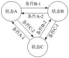
[0037] Such as image 3 The schematic diagram of the state transition template is shown, and the internal light state transition diagram of the body control unit in the single system function test category is used as an example to illustrate. When setting parameters, set the parameters A, B, C, A-1, B-1, C -1, A-2, B-2, and C-2 are set to specific states and conditions, state A is the state where the internal lights are off and all doors are closed, state B is the state that the internal lights are on and all doors are closed, and state C is The interior light is on and at least one door is open, condition A-1 is the ignition switch ON and all doors are closed, condition B-1 is the key is pulled out, condition C-1 is any door is open, and condition A-2 is ignition The switch is ON, the condition B-2 is the ignition switch OFF and all doors are closed, and the condition C-2 is the key is pulled out and any door is opened, the system will automatically generate test cases: Afte...

Embodiment 2

[0039]Taking the activation condition of the reversing image function in the vehicle integration function test category as an example, when setting the parameters, set the parameters D1, D2, D3, and E to the specific state and result, D1 is the ON gear of the ignition switch, and D2 is the R gear of the vehicle gear , D3 means that the vehicle speed is valid, E means that the reversing image function is turned on, and the system will automatically generate test cases: ① The ignition switch is ON, the vehicle gear is R, and the vehicle speed is valid at the same time, and the reversing image function is turned on. The vehicle gear is R and the vehicle speed is valid at the same time. As a result, the reversing image function cannot be turned on. ③ The ignition switch is ON, the vehicle gear is not R, and the vehicle speed is valid. The result is that the reversing image function cannot be turned on. ④ The ignition switch is ON, the vehicle The R gear and the invalid vehicle spee...

Embodiment 3

[0041] Taking the automatic locking function in the field of real vehicle function test as an example, when setting the parameters, set the parameters F, J, K, and L as specific variables, limits, results and minimum resolutions. The variable F is the vehicle speed, and J is 20km / h h, K is automatic lock, L is 1km / h, the system will automatically generate test cases: ①When the speed is equal to 20km / h, the result is automatically locked, ②When the speed is equal to 21km / h, the result is automatically locked, ③The speed is equal to 19km / h h, the result is not locked automatically.


PUM


Abstract

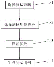
The invention discloses a method and system for generating electric function test case. The method comprises the steps of S1, selecting a test scope, S2, selecting a test case template, S3, setting test case parameters, and S4, generating a test case. The invention further provides a design system of the test case. The system comprises a test scope module, a test case template module, a parameter setting module and a test case generating module. The test scope module comprises three scopes which are actual vehicle function test, whole vehicle integrated function test and single system function test. The test case template module comprises five templates which are state transfer class, condition combination class, boundary value class, typical value class and custom class. The test case design method which is not reliant on the experience of a test engineer can guarantee the test coverage and test quality, and provide an effective solution and important basis for the design of the vehicle function test case.

Description

technical field [0001] The invention relates to the field of automobile electrical function test, in particular to a method and system for designing an electrical function test case. Background technique [0002] At present, in the functional testing of the automotive field, there is no mature theoretical basis for the design of electrical function test cases. The traditional test case design method is mainly based on technical documents, and design is based on the experience of test engineers. Since each test engineer has different experience, the design There are different degrees of differences in test cases, which may cause low coverage and reduce the risk of test quality, resulting in hidden dangers in the function and safety of automotive electrical appliances. [0003] In the field of automotive functional testing, a test case design method that does not cause differences in test cases due to different experience of test engineers is needed, which can ensure test cove...

Claims


Application Information

Patent Timeline
Patent Type & Authority Applications(China)
IPC IPC(8): G06F11/36
CPCG06F11/3684
Inventor 刘德利王邵龙孙运玺曹东芝孙久龙孙云谷原野李英节忠海高洪伟
Owner CHINA FIRST AUTOMOBILE
Learn More