
Vertical handover

Active Publication Date: 2008-03-13
NOKIA TECHNOLOGLES OY
View PDF23 Cites 37 Cited by
  • Summary
  • Abstract
  • Description
  • Claims
  • Application Information

AI Technical Summary

Benefits of technology

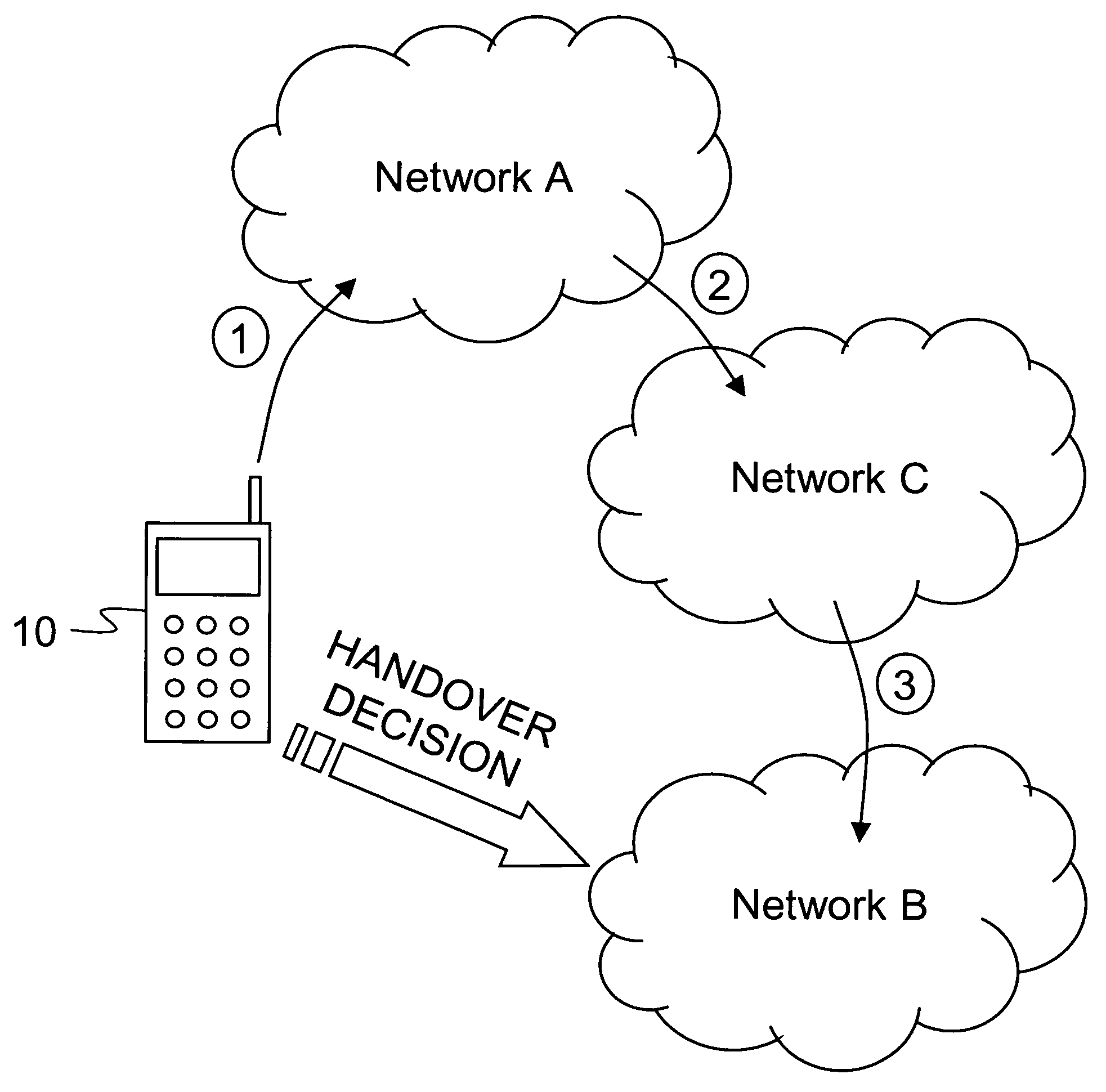
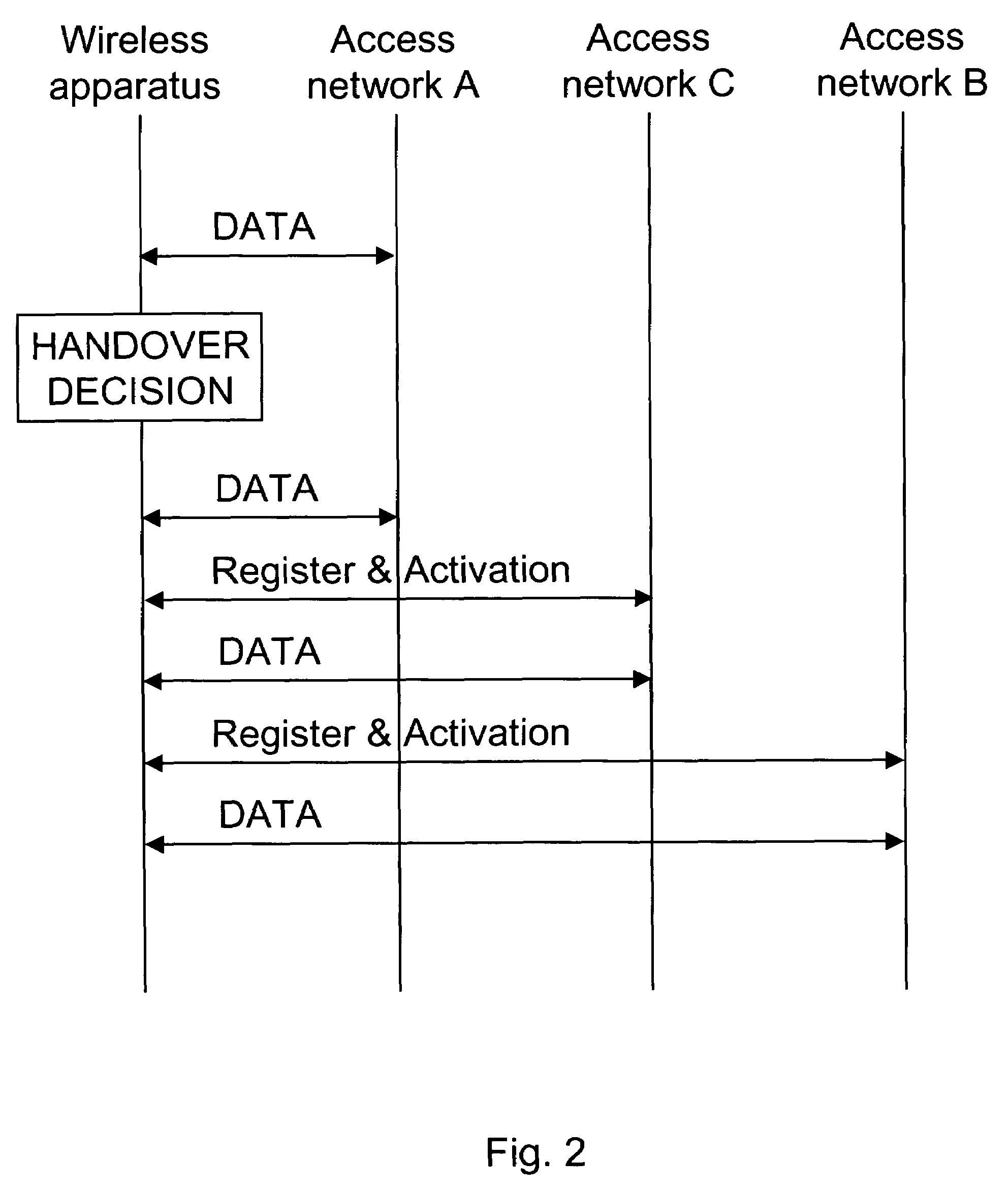
[0016]To support seamless handover and service continuity an embodiment of the invention proposes a mechanism according to which, in problematic cases where performing vertical handover from access network A to access network B, an intermediate access network C is used. An application connection is handed from A to C to B instead of directly from A to B. For example, when moving an application connection between operator and home WLAN networks, a cellular network may be used as an intermediate network. This decreases delay experienced by the application and the user, minimizes packet losses and negative effects which could have been experienced if the application connection had been directly handed from access network A to B.

Problems solved by technology

However, in many cases during handover, application connections may suffer from delay, packet losses, et cetera.
For example, a voice over IP (VoIP) application does not typically tolerate too long delays, or otherwise the voice quality suffers too much.
However, when performing a handover from a WLAN network to another WLAN network or between a WLAN network and a worldwide interoperability for microwave access (WiMAX) network, substantial delay (several seconds) may be introduced.
Current multi-radio mobile devices also have limitations affecting the handover procedure.
For example, two WLAN networks can not be active for one device at the same time (this would require two Rx / Tx pairs, however even this might lead into interference (for example, when two WLAN networks operate at the same / closely located channel)).
Also, WLAN and WiMAX networks can not be active at the same time, since there is too much interference, and / or same radio frequency (RF) components / pipes might be used for accessing both networks, and so on.
During this time, which may be several seconds, application data transmission is suspended and data packets sent to the mobile device would normally be lost.
It is also possible that even if the source and target access networks could be active at the same time on radio level, a configuration problem may occur, for example, an IP layer configuration may fail for the target access network (for example, the target access network might block access to service).
These kinds of problems are typically discovered only after taking the target access network into use, thus leading to increased delay and confusion from the application and user points of view.

Method used


Image

  • Vertical handover
  • Vertical handover
  • Vertical handover

Examples


Embodiment Construction

[0051]FIG. 1 shows a vertical handover scheme in accordance with an embodiment of the invention. In this embodiment, a wireless apparatus 10 lies within the service area of different access networks (A, B and C). The wireless apparatus 10 has been originally registered to the access network A in step 1. It is also assumed that the wireless apparatus has activated an application connection via access network A.

[0052]In an embodiment, the wireless apparatus 10 is a mobile terminal, mobile phone, a personal digital assistant (PDA) device with wireless access or a laptop computer. In another embodiment, the wireless apparatus 10 is any wireless device or wireless module or combination capable of wireless communication. The access networks A, B and C can be different access networks including but not limited to different WLAN networks (home WLAN, corporate WLAN, operator WLAN), cellular radio frequency networks including but not limited to GSM GPRS networks, WCDMA networks and 4G network...


PUM


Abstract

A vertical handover decision to perform a seamless vertical handover of a wireless apparatus from a current access network to a target access network is established. When deciding to perform the vertical handover from the current access network to the target access network it can be considered whether an intermediate access network could be used. It can be decided that first a seamless vertical handover is performed from the current access network to an intermediate access network, and subsequently a seamless vertical handover from the intermediate access network to the target access network is performed.

Description

FIELD OF THE INVENTION[0001]The present invention relates to vertical handover.BACKGROUND OF THE INVENTION[0002]Current wireless devices are able to access services via a number of different access technologies and networks. One may consider cost, quality of service (QoS), reliability, et cetera when selecting an access network to be used for an application level connection (application connection). For example, wireless local area network (WLAN) can be used for email downloads when such a known network is available, and otherwise a general packet radio service (GPRS) network or wideband code division multiple access (WCDMA) network can be used.[0003]When taking a new access network into use, several protocol layers and functions need to be configured. For example, when taking a WLAN access network into use, WLAN authentication and QoS negotiation may have to be done, and an internet protocol (IP) layer may have to configure a new IP address, a domain name system (DNS) name, et cete...

Claims


Application Information

Patent Timeline
IPC IPC(8): H04Q7/20H04W36/14H04W36/18
CPCH04W36/14H04W36/04H04W36/1446
Inventor FORSSELL, MIKASAROLAHTI, PASIYANG, FAN
Owner NOKIA TECHNOLOGLES OY
Learn More