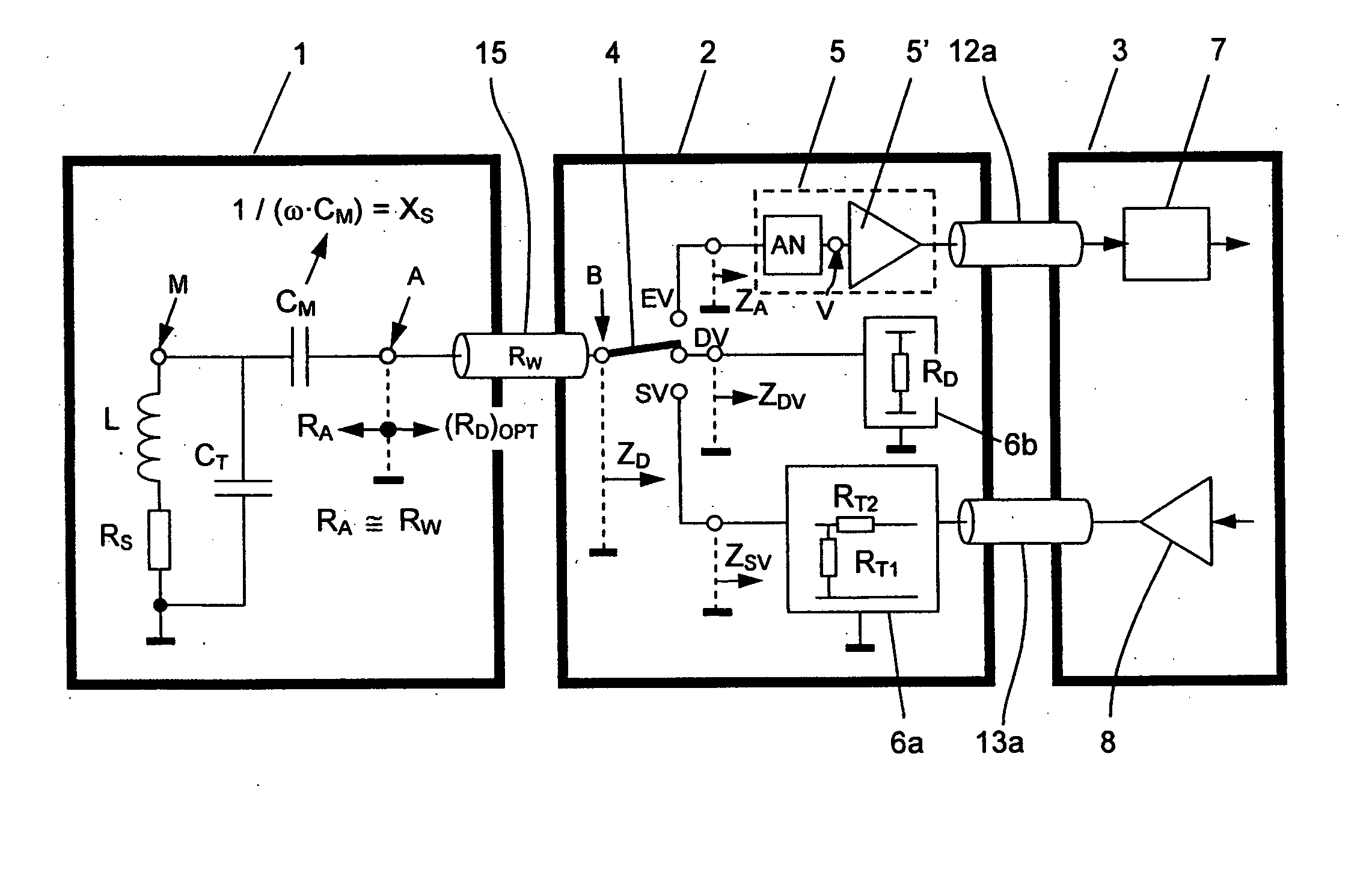
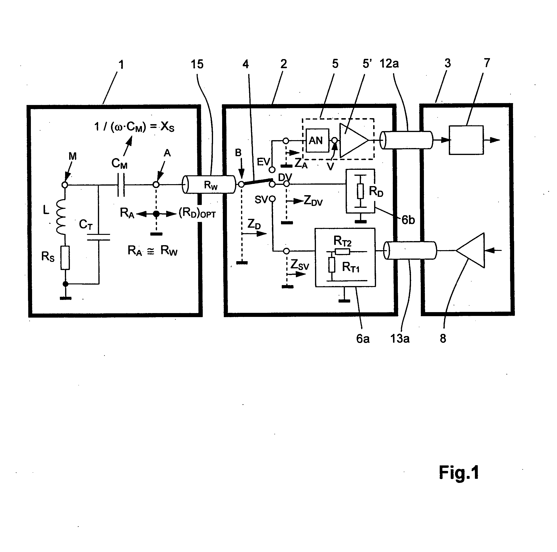
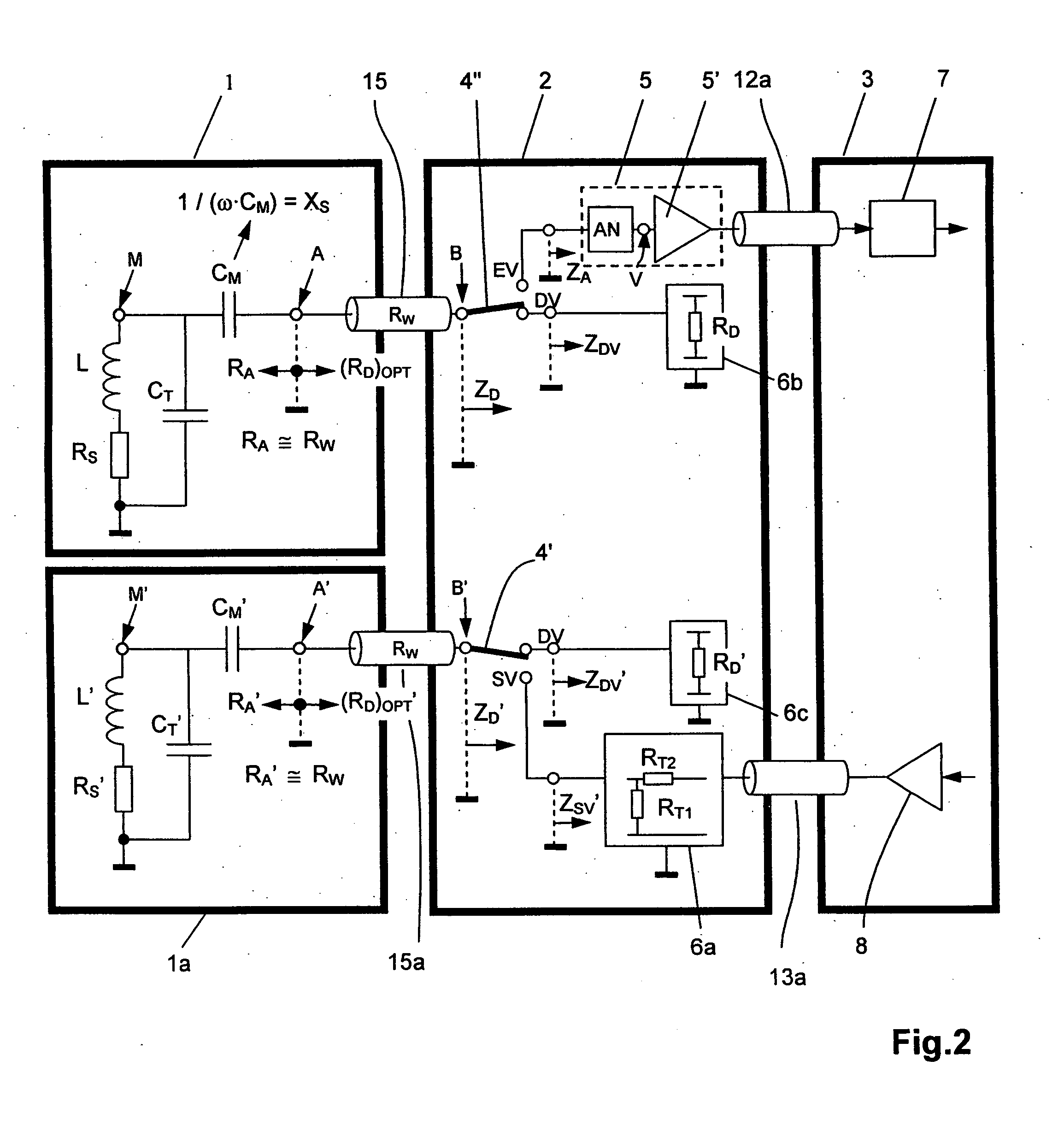
However, RF resonant circuits with high Q values are disadvantageous in that, during the transmitting process, the pulse-shaped transmission energy cannot be immediately received by the RF resonant circuit or be removed therefrom, since the RF resonant circuit requires both a certain build-up time as well as
decay time, which are longer the higher the Q value.
This is, however, not sufficient e.g. for NMR
spectroscopy applications.
Depending on the construction and the NMR frequency, the RF line may, however, also be very short compared to the
wavelength.
During transmission, the width of the NMR spectrum that can be excited is limited by the available bandwidth of the
transmission system and thereby, in particular, by the bandwidth of the RF resonant circuit used for transmission.
A very high Q value of the RF resonant circuit may cause the bandwidth of the RF resonant circuit to be too small to excite the desired frequency range of the magnetic
spins.
When this information is lost, the
base line and the shape of the NMR
resonance lines will be distorted in the NMR spectrum obtained after Fourier transformation (FT), and moreover the integral over the individual NMR lines can no longer be correctly calculated.
In addition to distortions in the spectrum, a long decay process also produces an undesired SINO loss, since no FID
signal can be acquired during the decay process, i.e. part of the FID
signal is lost.
The receiving process is a very complex process that substantially involves three problems:
In this case, the RF resonant circuit may react to this “resonant circuit”, which can cause broadenings, distortions and phase errors of the spectral lines.
The decay
signal of the
resonator in response to the transmission pulse is greatly reduced after damping but still has a residual portion that can cause distortions of the
base line in the NMR spectrum.
The third problem is caused when the Q value of the RF resonant circuit during the receiving process is too high for receiving the entire width of the desired NMR spectrum.
Such damping during the receiving process is only reasonable when the RF resonant circuit is also additionally damped during the transmission process, such that it yields the desired excitation bandwidth.
This configuration is disadvantageous in that the additional components (resistance RQ,
PIN diode DQ etc.) must be housed in the vicinity of the sensitive RF resonant circuit and can thereby deteriorate the homogeneity of the static
magnetic field due to their
magnetic susceptibility.
Additional wiring of the RF resonant circuit unavoidably reduces the Q value during the receiving process and thereby produces an undesired SINO loss.
This is possible only to a limited degree due to the “carrier-freeze-out-effect” in semiconductors, which is very problematic.
The Q switch cannot be directly used for damping the RF resonant circuit during the receiving process, since it would cause an excessive SINO loss.
This method also produces a SINO loss, since there is less time for
data acquisition.
It is only at the very end of the
decay time, that the electronic damping again becomes effective, but can no longer cause any significant reduction of the overall time of the decay process.
The RF resonant circuit is additionally loaded by the two adjustment paths during the transmission and receiving process, which nevertheless finally produces a SINO loss, mainly when the Q values of the RF resonant circuit are very high.
Moreover, in current NMR spectrometers comprising
high field superconducting magnets, it is practically not possible to closely arrange the RF resonant circuit and preamplifier, since there is no space for the preamplifier in the direct vicinity of the RF resonant circuit.
The
magnetic field strength of the
NMR magnet is also too high for unproblematic function of the preamplifier and moreover cryogenically cooled RF resonant circuits and preamplifiers require different cryogenic temperatures for optimum operation, i.e. both units would have to be thermally insulated from each other, which, in turn, would cause space problems.
Additionally, the above-described feedback of the preamplifier practically cannot be realized in today's
high field systems for reasons of stability.
For all above-mentioned reasons, the configuration disclosed in [2] is not suitable for today's
high field NMR spectrometers.
This is, however, far too little for today's high field systems.
Moreover, with large “overcoupling”, undesired effects occur, e.g. saturation effects in the preamplifier and the decay times can increase again.
The above-described prior art only provides solutions with electronic damping impedances (input impedances of preamplifiers) for the damping process and when damping is performed at the
low impedance point A of the RF resonant circuit, which do not optimally damp the RF resonant circuit due to their non-linear properties, since damping acts, in particular, only when the amplitude of the oscillation has become sufficiently small that it is in the
linear range of the preamplifier.
The conventional proposed solutions merely present individual solutions which are either optimized for the transmission and damping process or for the receiving process, but do not provide a comprehensive solution that provides optimum relationships in all three processes.


